
Reassessment of the Stability Conditions in the Lignite Open Pits of Oltenia (Romania) in Relation to the New Local Seismic Context as an Imperative for Sustainable Mining

Abstract
:1. Introduction
2. General Geology and Local Tectonics
2.1. Geology and Stratigraphy of the Region
2.2. Tectonics
2.2.1. Tectonics of the Rovinari Mining Sub-Basin
2.2.2. Tectonics of the Jilț Mining Sub-Basin
2.2.3. Tectonics of the Berbeşti Mining Sub-Basin
3. Seismic Framing of the Area
3.1. Current Seismic Framing
3.2. Description of Seismic Activity in 2023
- over 30 earthquakes with a magnitude between 3–3.9 ML;
- nine earthquakes with a magnitude between 4–4.9 ML: 4.1 ML (3.2 Mw)—14 February 2023, 4.2 ML (3.3 Mw)—16 February 2023, 4.3 ML (3.3 Mw)—17 February 2023, 4 ML (3.2 Mw)—22 February 2023, 4.9 ML (4.4 Mw) 20 March 2023, 4.2 ML (3.3 Mw)—19 June 2023, 4.2 ML (3.3 Mw)—18 July 2023; 4.5 ML (3.3 MW)—21 August 2023; 4.3 ML (3.3 Mw)—10 November 2023;
- two earthquakes with magnitude ≥5 ML: 5.2 ML (4.8 Mw)—13 February 2023 and 5.7 ML (5.4 Mw)—14 February 2023.

- GZR—Gura Zlata;
- HERR—Băile Herculane;
- MHISU—Drobeta-Turnu Severin;
- RMGR—Halânga;
- SRE—Strehaia.

4. Considerations on the Stability of Mining Workings under the New Seismic Conditions
4.1. Peșteana North Open Pit
4.1.1. Analysis Sections and Rocks Characteristics
4.1.2. Results of the Stability Analyses
4.2. Jilț North Open Pit
4.2.1. Analysis Sections and Rocks Characteristics
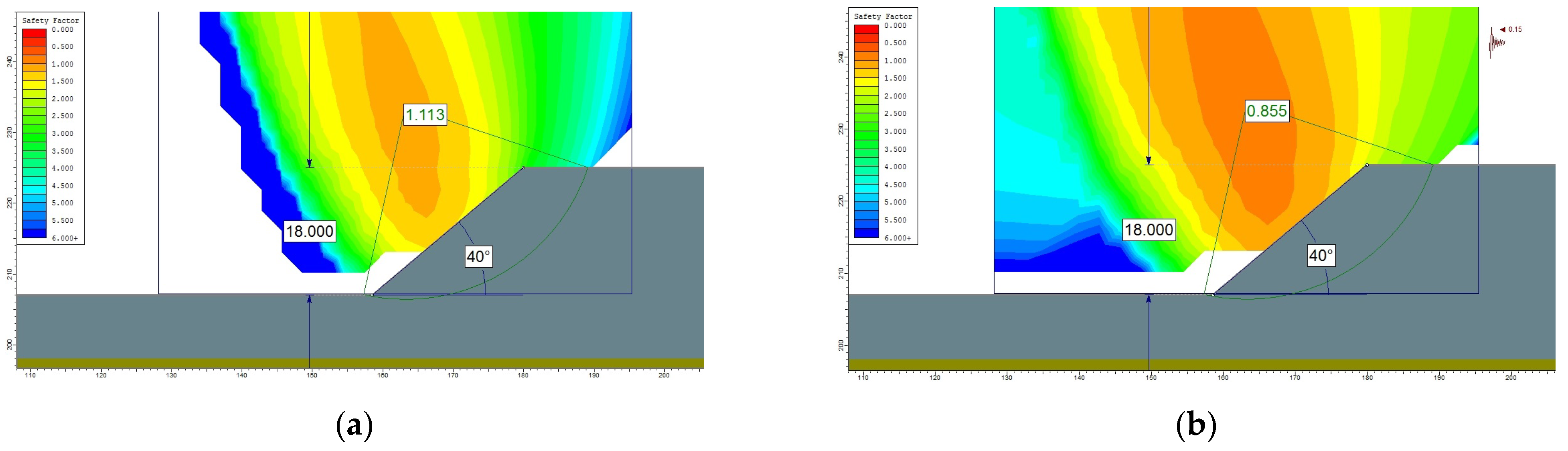
4.2.2. Results of the Stability Analyses
4.3. Berbești–Alunu Mining Perimeter (Alunu Open Pit and West Berbești Dump)
4.3.1. Analysis Sections and Rocks Characteristics
4.3.2. Results of the Stability Analyses
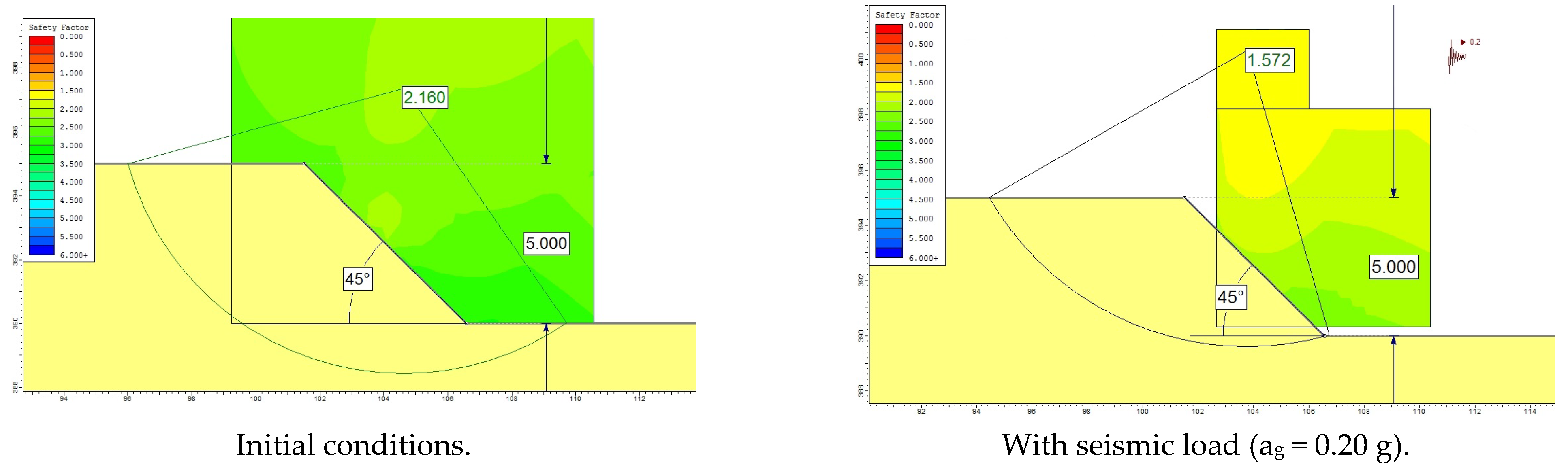
- for the individual steps excavated in the yellow-brown clay (T1–T8) the value of the stability factor remains above unit, presenting a stability reserve of over 50%, i.e., the condition Fs ≥ 1.3 being satisfied, for slopes with a long duration of remaining in place. This fact is due to the geometry adopted for these steps, more precisely due to their low height (5 m);
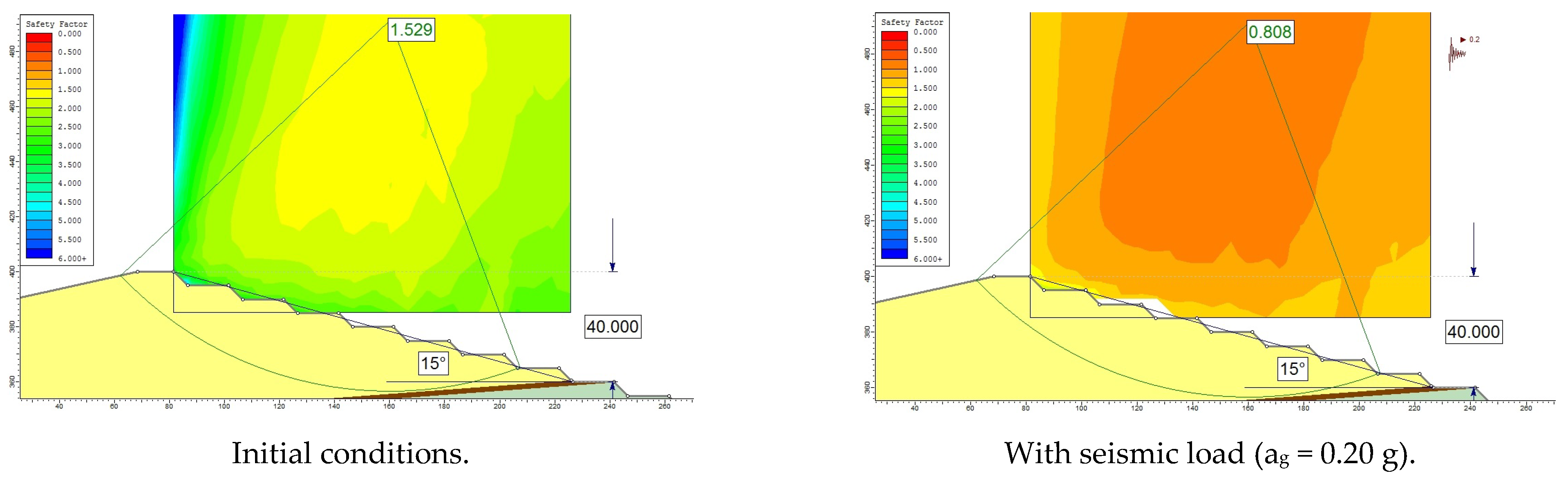
- for the system of steps dug in the yellow-brown clay (T1–T8), the value of the stability factor becomes sub-unit, which indicates its transition into a state of imbalance (unstable slope).This potential situation is the most dangerous because it is observed that the slide develops on a total height of 40 m which is divided into eight steps of excavation with classic excavators (this means that there are several excavators and dumping trucks on each step working simultaneously). This results in endangering a large number of machines, but more importantly in threatening the lives of numerous workers. This is why this particular situation will be analyzed with priority in a future study (from the point of view of resizing the work fronts so that the stability conditions are met even in the case of the occurrence of an earthquake). In principle, the solution would be to increase the width of the working berms;
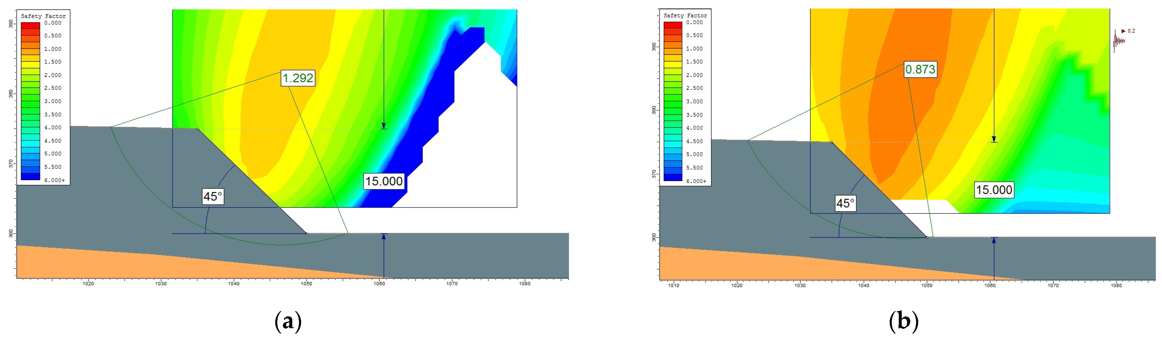
- for the TH1 step of the interior dump under the same seismicity conditions, the value of the stability factor remains above unit, but the determined stability reserve is below 10%. Such a stability reserve is considered by specialized literature [25,26,27,63,68] to be non-compliant, especially for slopes with a medium or long duration of remaining in place, being at the limit in the situation of slopes with a short duration of remaining in place;
- for step TH2 of the internal dump, the value of the stability factor drops below 1, which indicates its transition into a state of imbalance (unstable slope).
5. Final Conclusions
Author Contributions
Funding
Institutional Review Board Statement
Informed Consent Statement
Data Availability Statement
Conflicts of Interest
References
- Lazăr, M.; Faur, F.; Apostu, I.M. Stability conditions in lignite open pits from Romania. Case study: Oltețu open pit. Appl. Sci. 2022, 12, 9607. [Google Scholar] [CrossRef]
- Faur, F.; Lazăr, M.; Apostu, I.M.; Brujan, M. Verifying the Stability of the Working Fronts of Lignite Open Pits Developed in Hilly Areas—A Case Study of Jilț North Open Pit (Romania). Appl. Sci. 2023, 13, 11480. [Google Scholar] [CrossRef]
- Steiakakis, E.; Kavouridis, K.; Monopolis, D. Large scale failure of the external waste dump at the “South Field” lignite mine, 607 Northern Greece. Eng. Geol. 2009, 104, 269–279. [Google Scholar] [CrossRef]
- Ylber, M. Evaluation of landslides and engineering measures on lignite open pit slope in south east Sibovc-Kosovo Coal Basin. In Proceedings of the Landslide and Flood Hazard Assessment, 1st Regional Symposium on Landslides in the Adriatic-Balkan Region and 3rd Workshop of the Japanese-Croatian Project “Risk Identification and Land-Use Planning for Disaster Mitigation of Landslides and Floods in Croatia”, Zagreb, Croatia, 6–9 March 2013; Arbanas, S.M., Arbanas, Z., Eds.; City of Zagreb Emergency Management Office: Zagreb, Croatia, 2013; Volume 1. [Google Scholar]
- Bednarczyk, Z. Slope instabilities in Polish open-pit mines. In Landslides and Engineered Slopes. Experience, Theory and Practice, 1st ed.; CRC Press Taylor and Francis Group: New York, NY, USA, 2016; 9p. [Google Scholar] [CrossRef]
- Steiakakis, C.; Apostolou, E.; Papavgeri, G.; Agioutantis, Z.G.; Schilizzi, P. Large moving landslide inside a lignite mine in northern Greece. In Landslides and Engineered Slopes. Experience, Theory and Practice; Aversa, S., Cascini, L., Picarelli, L., Scavia, C., Eds.; CRC Press Taylor and Francis Group: New York, NY, USA, 2016; Volume 222, 8p. [Google Scholar] [CrossRef]
- Steiakakis, E.; Thalassinakis, J.; Agioutantis, Z.G.; Galetakis, M. Failure process of the external waste dump of a lignite mine using FEM. In Proceedings of the 13th International Symposium Continuous Surface Mining (ISCSM 2016), Belgrade, Serbia, 12–14 September 2016. [Google Scholar]
- Baumann, A.B.G. Landslides from Space—Amyntaio Lignite Coal Mine Landslide (10th June 2017); Data Set, Zenodo, European Organization for Nuclear Research: Meyrin, Switzerland, 2017. [Google Scholar] [CrossRef]
- Vanneschi, C.; Eyre, M.; Burda, J.; Žižka, L.; Francioniac, M.; Coggan, J.S. Investigation of landslide failure mechanisms adjacent to lignite mining operations in North Bohemia (Czech Republic) through a limit equilibrium/finite element modelling approach. Geomorphology 2018, 320, 142–153. [Google Scholar] [CrossRef]
- Chen, T.; Shu, J.; Han, L.; Tovele, G.S.V.; Li, B. Landslide mechanism and stability of an open-pit slope: The Manglai open-pit coal mine. Front. Earth Sci. 2023, 10, 1038499. [Google Scholar] [CrossRef]
- Zevgolis, I.; Deliveris, A.; Koukouzas, N. Slope failure incidents and other stability concerns in surface lignite mines in Greece. J. Sustain. Min. 2019, 18, 182–197. [Google Scholar] [CrossRef]
- Islam, S.; Hosain, M.; Islam, M.S.; Ahmed, D.; Hoque, F.; Karim, S.U.; Islam, A. Disaster due to slope failure in the Pahartoli area of the Chittagong city, Bangladesh. Int. J. Sci. Eng. Res. 2015, 6, 246–251. Available online: https://www.ijser.org/paper/Disaster-due-to-slope-failure-in-the-Pahartoli-Area-of-the-Chittagong-city.html (accessed on 12 September 2023).
- Ortiz, R.; Silva, R.; Michalak, N. Application of the Response Surface Methodology to 3DEC Analysis of Open Pit Slopes. In Proceedings of the 8th South American Congress on Rock Mechanics, Buenos Aires, Argentina, 15–18 November 2015. [Google Scholar]
- Dongping, D.; Li, L.; Zhao, L. Limit equilibrium method (LEM) of slope stability and calculation of comprehensive factor of safety with double strength-reduction technique. J. Mount. Sci. 2017, 14, 2311–2324. [Google Scholar] [CrossRef]
- Kolapo, P.; Oniyide, G.O.; Said, K.O.; Lawal, A.I.; Onifade, M.; Munemo, P. An Overview of Slope Failure in Mining Operations. Mining 2022, 2, 350–384. [Google Scholar] [CrossRef]
- Kavvadas, M.; Roumpos, C.; Servou, A.; Paraskevis, N. Geotechnical Issues in Decommissioning Surface Lignite Mines—The Case of Amyntaion Mine in Greece. Mining 2022, 2, 278–296. [Google Scholar] [CrossRef]
- Crosta, G.; Agliardi, F.; Rivolta, C.; Alberti, S.; Dei Cas, L. Long-term evolution and early warning strategies for complex rockslides by real-time monitoring. Landslides 2017, 14, 1615–1632. [Google Scholar] [CrossRef]
- Aditiana, A.; Kubotab, T.; Shinoharab, Y. Comparison of GIS-based landslide susceptibility models using frequency ratio, logistic regression, and artificial neural network in a tertiary region of Ambon, Indonesia. Geomorphology 2018, 318, 101–111. [Google Scholar] [CrossRef]
- Pecoraro, G.; Calvello, M.; Piciullo, L. Monitoring strategies for local landslide early warning systems. Landslides 2019, 16, 213–231. [Google Scholar] [CrossRef]
- Intrieri, E.; Carlà, T.; Gigli, G. Forecasting the time of failure of landslides at slope-scale: A literature review. Earth-Sci. Rev. 2019, 193, 333–349. [Google Scholar] [CrossRef]
- Chen, M.; Jiang, Q. An early warning system integrating time-of-failure analysis and alert procedure for slope failures. Eng. Geol. 2020, 272, 105629. [Google Scholar] [CrossRef]
- Mohmmed, M. A review on slope monitoring and application methods in open pit mining activities. Int. J. Sci. Technol. Res. 2021, 10, 181–186. [Google Scholar]
- Shang, L.; Nguyen, H.; Bui, X.N.; Vu, T.H.; Costache, R.; Hanh, L.T.M. Toward state-of-the-art techniques in predicting and controlling slope stability in open-pit mines based on limit equilibrium analysis, radial basis function neural network, and brainstorm optimization. Acta Geotech. 2022, 17, 1295–1314. [Google Scholar] [CrossRef]
- Martireni, A.P.; Suryadi, S.; Tohari, A.; Soebowo, E.; Wibawa, S.; Hermawan, K.; Sugianti, K.; Syahbana, A.J. Wahyudin, Rock slope stability monitoring system in the Batu Mountain area, Lembang, West Bandung. BIO Web Conf. 2023, 73, 04008. [Google Scholar] [CrossRef]
- Duncan, J.M.; Wright, S.G.; Brandon, T.L. Soil Strength and Soil Stability, 2nd ed.; JohnWiley & Sons, Inc.: Hoboken, NJ, USA, 2014; 317p, Available online: https://istasazeh-co.com/wp-content/uploads/2021/11/Soil-Strength-and-Slope-Stability-1.pdf (accessed on 15 September 2023).
- Duncan, C.W. Rock Slope Engineering. Civil and Mining, 5th ed.; CRC Press—Taylor & Francis Group: New York, NY, USA, 2018; 620p, Available online: https://www.routledge.com/Rock-Slope-Engineering-Civil-Applications-Fifth-Edition/Wyllie/p/book/9781498786270 (accessed on 19 September 2023).
- Stănciucu, M. Stability of Natural and Artificial Slopes (In Romanian); Technical: Bucharest, Romania, 2018; pp. 11–150. [Google Scholar]
- Li, C.; Li, L.; Cheng, Y.; Xu, L.; Yu, G. Seismic reliability analysis of slope in spatially variable soils using multiple response surfaces. Eng. Comput. 2023, 40, 2940–2961. [Google Scholar] [CrossRef]
- Thejaswini, R.M.; Govindaraju, L. Seismic Behavior of Stepback Buildings with Slope Stability: An Empirical–Numerical Study. Geotech. Geol. Eng. 2023, 22. [Google Scholar] [CrossRef]
- Belazouz, L.; Bouzelha, K.; Hammoum, H.; Amiri, O.; Khelil, N. Reliability Analysis of the Slope Stability of Homogeneous Earth Dam under Seismic Loading. Per. Polytech. Civ. Eng. 2023, 68, 107–121. [Google Scholar] [CrossRef]
- Mahmood, K.; Rehman, Z.; Farooq, K.; Memon, S.A. One dimensional equivalent linear ground response analysis—A case study of collapsed Margalla Tower in Islamabad during 2005 Muzaffarabad Earthquake. J. Appl. Geophys. 2016, 130, 110–117. [Google Scholar] [CrossRef]
- Mahmood, K.; Zamin, B.; Iqbal, S.; Rehman, Z.; Afzal, S.; Safdar, M.; Iqbal, Q.; Ali, A. Local site effect on seismic hazard of the relocated new Balakot town. Soil Dyn. Earthq. Eng. 2022, 162, 107451. [Google Scholar] [CrossRef]
- Rodriguez, C.E.; Bommer, J.J.; Chandler, R.J. Earthquake-induced landslides: 1980–1997. Soil Dyn. Earthq. Eng. 1999, 18, 325–346. [Google Scholar] [CrossRef]
- Durrheim, R.J.; Anderson, R.L.; Cichowicz, A.; Ebrahim-Trollope, R.; Hubert, G.; Kijko, A.; McGarr, A.; Ortlepp, W.D.; van der Merwe, N. The Risks to Miners, Mines, and the Public posed by Large Seismic Events in the Gold Mining Districts of South Africa. In Proceedings of the Third International Seminar on Deep and High Stress Mining, Quebec City, QC, Canada, 2–4 October 2006; Available online: https://api.semanticscholar.org/CorpusID:110240632 (accessed on 7 November 2023).
- Azhari, A. Evaluating the Effect of Earthquakes on Open Pit Mine Slopes. Ph.D. Thesis, Colorado School of Mines, Golden, CO, USA, 2016. Available online: https://repository.mines.edu/handle/11124/170619 (accessed on 7 November 2023).
- Lorig, L. Designing for extreme events in open pit slope stability. J. S. Afr. Inst. Min. Metall. 2016, 116, 387–398. [Google Scholar] [CrossRef]
- Ruge, J.C.; Molina-Gómez, F.; Rojas, J.P. Thixotropic behaviour study of clayey soils from the lacustrine deposits of Bogotá high plateau. J. Phys. Conf. Ser. 2019, 1386, 012050. [Google Scholar] [CrossRef]
- Faur, F.; Lazăr, M.; Apostu, I.M. Land Stability in the Influence Areas of Lignite Open Pits. A Case Study for the Berbești Mining Basin (Romania); Lambert Academic Publisher: London, UK, 2022; 108p. [Google Scholar]
- Andreescu, I.; Ţicleanu, N.; Pană, I.; Pauliuc, S.; Pelin, M.; Barus, T. Stratigraphie des dépôts pliocènes à charbons, zone est d’Oltenie (secteur Olt-Jiu). An. Univ. Buch. Geol. 1985, 34, 87–96. [Google Scholar]
- Ţicleanu, N.; Roman, S.; Givulescu, R.; Biţoianu, C. Considérations paléofloristiques et pétrographiques sur la génèse des lignites de l’ouest d’Olténie. D.S. Inst. Geol. Geof. 1985, 69, 71–87. [Google Scholar]
- Apostu, I.M. Geotechnical Risks in the Conditions of Flooding of Remaining Gaps of Lignite Open Pits (in Romanian); Universitas PH: Petroșani, Romania, 2021; 281p. [Google Scholar]
- Smeu, A.C. Efficient Solutions for the Construction and Management of Sterile Dumps from the Rovinari and Motru Mining Basins for Rendering into the Economic Circuit (in Romanian). Ph.D. Thesis, University of Petrosani, Petrosani, Romania, 2012. [Google Scholar]
- Brujan, M.; Rotunjanu, I. Assessment of the impact of mining activities from the open pits of the Jilț basin on land surfaces and rehabilitation solutions. In Proceedings of the 6th Balkan Mining Congress (in Romanian), Petroșani, Romania, 20–25 September 2015. [Google Scholar]
- Pleșea, V.; Radu, S.M.; Vereș, I.; Eremia, M.; Popa, V. Competitive solutions of underground working support aligned with the conditions of high use and performance in exploitation and use of coal for energy production. An. ‘C-tin Brancusi’ Univ. Tg-Jiu Eng. Ser. 2015, 2, 136–145. Available online: https://www.utgjiu.ro/revista/ing/pdf/2015-2/16_Valeriu%20Plesea.pdf (accessed on 6 September 2023).
- Fodor, D.; Dican, N. Open pit exploitation of coal deposits from Berbeşti mining basin. Min. Rev. 2013, 19, 2–11. Available online: https://www.upet.ro/revistaminelor/archive/rmpdf2013/nr2en.html (accessed on 25 October 2023).
- Chiriță, R.V.; Lazăr, M.; Faur, F. Critical analysis of the geomorphological changes as a result of mining activities in Berbeşti basin. An. Univ. Petr. Min. Eng. 2018, 19, 132–145. Available online: https://www.upet.ro/annals/mining/pdf/Annals%20of%20UPET%20-%20Mining%20Engineering%20Vol%2019-2018%20(XLVI).pdf (accessed on 22 November 2023).
- Law No. 575/22 October 2001 regarding the National territory development plan—Section V—Natural risk areas (in Romanian). 2001.
- Seismic Design Code P 100-1—2013 (in Romanian). Technical University of Civil Engineering Bucharest, Bucharest, Romania. 2013. Available online: https://www.encipedia.org/articole/proiectare/resurse-utile/harti-de-zonare/harta-de-zonare-seismica-din-p100-1-2013.html (accessed on 10 August 2023).
- Popa, M.; Chircea, A.; Dinescu, R.; Neagoe, C.; Grecu, B.; Borleanu, F. Romanian Earthquake Catalogue (ROMPLUS). Mendeley Data, V2. 2022. [Google Scholar] [CrossRef]
- INCDFP. Seismicity of the Oltenia, Gorj Area: Tectonics, Causes and Characteristics (in Romanian). Communicate from 11th of April 2023. Available online: http://www.infp.ro/index.php?i=nws&year=2023&id=59&news_title=Comunicat:%20Seismicitatea%20zonei%20Oltenia,%20Gorj:%20tectonic%C4%83,%20cauze%20%C8%99i%20caracteristici (accessed on 26 August 2023).
- Peptan, C.; Holt, A.G.; Iana, S.A.; Sfinteș, C.; Iov, C.A.; Mărcău, F.C. Considerations of the Impact of Seismic Strong Ground Motions in Northern Oltenia (Romania) on Some Indicators of Sustainable Development Characterization of the Region from a Security Perspective. Sustainability 2023, 15, 12865. [Google Scholar] [CrossRef]
- Richter, C.F. An Instrumental Earthquake Magnitude Scale, Bulletin of the Seismological Society of America. Bull. Seism. Soc. Am. 1935, 25, 1–32. [Google Scholar] [CrossRef]
- Gutenberg, B.; Richter, C.F. Magnitude and energy of earthquakes. Ann. Geophys. 1956, 9, 795. Available online: http://authors.library.caltech.edu/43574/1/Gutenberg_1956.pdf (accessed on 10 October 2023).
- Malagnini, L.; Munafò, I. On the Relationship between ML and Mw in a Broad Range: An Example from the Apennines, Italy. Bull. Seism. Soc. Am. 2018, 108, 1018–1024. [Google Scholar] [CrossRef]
- Spence, W.; Sipkin, S.A.; Choy, G.L. Measuring the size of an Earthquake. Earthq. Volc. 1989, 21, 58–63. Available online: https://pubs.usgs.gov/unnumbered/70039068/report.pdf (accessed on 10 October 2023).
- Tiganescu, A.; Grecu, B.; Marmureanu, A.; Ionescu, C. Strong ground motion parameters of the ML 5.2 and ML 5.7 crustal earthquakes in Gorj, Romania. Preliminary Report, National Institute for Earth Physics (Romania). 2023. Available online: https://www.researchgate.net/publication/368667058_Strong_ground_motion_parameters_of_the_ML_52_and_ML_57_crustal_earthquakes_in_Gorj_Romania (accessed on 26 September 2023).
- Stelea, I. Comments on the supragetic nappe in the central-eastern south Carpathians. Oltenia J. Stud. Nat. Sci. 2016, 32, 7–11. Available online: http://olteniastudiisicomunicaristiintelenaturii.ro/cont/32_1/01_Stelea.pdf (accessed on 14 November 2023).
- Gorj Online. Press Release from 26 March 2023. Available online: https://www.gorjonline.ro/exclusiv-parerea-specialistilor-dupa-seismele-din-gorj-ne-putem-astepta-la-un-cutremur-de-65-pe-scara-richter/ (accessed on 26 September 2023).
- Apostu, I.M.; Lazar, M.; Faur, F. A Suggested Methodology for Assessing the Failure Risk of the Final Slopes of Former Open-Pits in Case of Flooding. Sustainability 2021, 13, 6919. [Google Scholar] [CrossRef]
- Faur, F.; Lazăr, M.; Apostu, I.M.; Rada, C.; Moisuc-Hojda, D. Assessment of the Stability State and the Risk of Landslides within Berbești Mining Basin (Romania) Post Closure. Inży. Min. J. Polish Min. Eng. Soc. 2022, 2, 59–70. [Google Scholar] [CrossRef]
- Brujan, M.; Faur, F.; Lazăr, M.; Apostu, I.-M. Analysis of the Stability State of Jilț North Internal Dump in the Perspective of its Ecological Reconstruction. Min. Rev. 2023, 29, 1–13. [Google Scholar] [CrossRef]
- Toderas, M.; Florea, V.A.; Itu, R.B. Stability Analysis of the Tailings Dam for the Purpose of Closing, Greening, and Ensuring Its Safety—Study Case. Sustainability 2023, 15, 7606. [Google Scholar] [CrossRef]
- Hoek, E.; Bray, J.W. Rock Slope Engineering, 3rd ed.; Institution of Mining and Metallurgy: London, UK, 1981; 364p. [Google Scholar] [CrossRef]
- Derek, H.C. Landslides in Practice: Investigation, Analysis, and Remedial/Preventative Options in Soils; John Wiley & Sons, Inc.: Hoboken, NJ, USA, 2005; pp. 170–219. [Google Scholar]
- Huang, Y.H. Slope Stability Analysis by the Limit Equilibrium Methods: Fundamentals and Methods; ASCE Press: New York, NY, USA, 2014; pp. 229–264. [Google Scholar] [CrossRef]
- Salgado, R. The Engineering of Foundation Slopes and Retaining Structures, 2nd ed.; CRC Press: Boca Raton, FL, USA, 2022; pp. 894–917. [Google Scholar]
- RocScience, Inc. Slide 2D Limit Equilibrium Slope Stability Program [User’s Guide], Version 6.0.2.5. 2013. Available online: www.rocscience.com (accessed on 5 October 2023).
- Rotunjanu, I. Stability of Natural and Anthropogenic Slopes; Infomin PH: Deva, Romania, 2005. (In Romanian) [Google Scholar]
- Ministry of Labor and Social Protection. Technical Regulations on “Specific Labor Protection Norms for Coal and Bituminous Shale Mines; Ministry of Labor and Social Protection: Bucharest, Romania, 1997. (In Romanian) [Google Scholar]
- Liu, X.; Tang, H.; Xiong, C.-R.; Liu, Q.B. A new method for reliability analysis of dynamic slope stability with considering energy-time distribution. Rock Soil Mech. 2015, 36, 1428–1443+1454. Available online: https://www.cnki.net/kcms/doi/10.16285/j.rsm.2015.05.027.html (accessed on 12 September 2023).
- Liu, F.; Yang, T.; Zhou, J.; Deng, W.; Yu, Q.L.; Zhang, P.; Cheng, G. Spatial variability and time decay of rock mass mechanical parameters: A landslide study in the Dagushan open-pit mine. Rock Mech. Rock Eng. 2020, 53, 3031–3053. [Google Scholar] [CrossRef]
- Liu, G.; Huang, Y.; Cao, B.; Yao, Y. Dynamic control of working slope shape and optimization of advance speed in seasonally stripped open-pit coal mine. Coal Sci. Techn. 2023, 51, 45–54. Available online: http://www.mtkxjs.com.cn/en/article/doi/10.13199/j.cnki.cst.2023-0621 (accessed on 12 September 2023).
- Boujaj, A.; Lahcen, B.; Ouadif, L.; Khadija, B. A methodology based on GIS for 3D slope stability analysis. Int. J. Eng. Technol. 2016, 8, 2259–2264. [Google Scholar] [CrossRef]
- Yu, G.; Xie, M.; Liang, J.; Farooq, A.; Williams, E.J. A GIS-based 3D slope stability analysis method based on the assumed normal stress on the slip surface. Sci. Rep. 2020, 10, 4442. [Google Scholar] [CrossRef] [PubMed]
- Nguyen, P.M.V.; Wrana, A.; Rajwa, S.; Różański, Z.; Frączek, R. Slope Stability Numerical Analysis and Landslide Prevention of Coal Mine Waste Dump under the Impact of Rainfall—A Case Study of Janina Mine, Poland. Energies 2022, 15, 8311. [Google Scholar] [CrossRef]
- Kadlíček, T.; Mašín, D. Surface layer method for analysis of slope stability using finite elements. Comput. Geotech. 2023, 164, 105799. [Google Scholar] [CrossRef]
- Díaz-Durán, F.A. Slope Stability in Open Pits with Thin Weak Layers. In Proceedings of the Rocscience International Conference (RIC 2023), Toronto, ON, Canada, 24–26 April 2023. [Google Scholar] [CrossRef]
- McQuillan, A.; Guy, G. The Evolution and Application of 3D Limit Equilibrium Modelling to Assessing Open Cut Coal Mine Slope Stability. Available online: https://encompassmining.com/wp-content/uploads/2023/06/Revolutionizing-Open-Cut-Coal-Mine-Slope-Stability-Assessment-with-3D-Modelling_McQuillan-Guy-GG.pdf (accessed on 17 August 2023).
- Han, C.X.; Hou, T.S.; Chen, Y. Three-dimensional slope stability and anti-slide pile treatment of Zhangjiayao landslide under rainfall. Eng. Comput. 2023, 40, 2667–2692. [Google Scholar] [CrossRef]
- Seidu, M.; Andrews, P. Using a 3D Limiting Equilibrium Modelling Tool for Slope Stability in Weathered Rocks: A Case Study. In Proceedings of the Rocscience International Conference (RIC 2023), Toronto, ON, Canada, 24–26 April 2023. [Google Scholar] [CrossRef]
- Li, S.; Zhao, Z.; Hu, B.; Yin, T.; Chen, G.; Chen, G. Three-Dimensional Simulation Stability Analysis of Slopes from Underground to Open-Pit Mining. Minerals 2023, 13, 402. [Google Scholar] [CrossRef]
- Sun, S.; Liu, L.; Yang, Z.; Fu, X. Toward a sound understanding of a large-scale landslide at a mine waste dump, Anshan, China. Landslides 2023, 20, 2583–2602. [Google Scholar] [CrossRef]
- Luo, W.; Gong, Z. Application of Rosenblueth moment estimation method into probability analysis of slope stability. Chin. J. Rock Mech. Eng. 2003, 2, 232–235. Available online: https://caod.oriprobe.com/articles/5692393/APPLICATION_OF_ROSENBLUETH_MOMENT_ESTIMATION_METHOD_INTO_PROBABILISTIC.htm (accessed on 15 August 2023).
- Da Costa, K.R.C.B.; Dantas, A.P.N.; Cavalcante, A.L.B.; Assis, A.P. Probabilistic Approach to Transient Unsaturated Slope Stability Associated with Precipitation Event. Sustainability 2023, 15, 15260. [Google Scholar] [CrossRef]
- Kumar, A.; Das, S.K.; Nainegali, L.; Raviteja, K.V.N.S.; Reddy, K.R. Probabilistic Slope Stability Analysis of Coal Mine Waste Rock Dump. Geotech. Geol. Eng. 2023, 41, 4707–4724. [Google Scholar] [CrossRef]
- Kumar, A.; Das, S.K.; Nainegali, L.; Reddy, K.R. Slope Stability Analysis of Coalmine Overburden Dump Using a Probabilistic Approach. In Geoenvironmental and Geotechnical Issues of Coal Mine Overburden and Mine Tailings; Springer Transactions in Civil and Environmental, Engineering; Das, S.K., Reddy, K.R., Nainegali, L., Jain, S., Eds.; Springer: Singapore, 2023. [Google Scholar] [CrossRef]
- Doderovic, A.; Doderovic, S.M.; Stepanovic, S.; Bankovic, M.; Stevanovic, D. Hybrid Model for Optimisation of Waste Dump Design and Site Selection in Open Pit Mining. Minerals 2023, 13, 1401. [Google Scholar] [CrossRef]
- Enkhbold, B.; Ikeda, H.; Toriya, H.; Adachi, T. A Comprehensive Numerical Modeling Study for Parameter Optimization and Slope Stability Analysis in the Baganuur Lignite Coal Mine. Mining 2023, 3, 755–772. [Google Scholar] [CrossRef]


| Period | Epoch | Description | ||
|---|---|---|---|---|
| QUATERNARY | Holocene | recent alluvium of the valleys, proluvial and colluvial deposits, gravels | ||
| Pleistocene | sands and gravels with intercalations of clays, sandy clays, clayey sands, thin layers of lignite (Lower Pleistocene), sands and gravels of the high, middle and lower terraces | |||
| PLIOCENE | Romanian | Superior | sands and gravel in which the XIV–XVII lignite strata are intercalated | |
| Inferior | clays and fine sands in which the VIII–XIII lignite strata are intercalated | |||
| Dacian | Superior | alternation of clays with gray and green sandy clays, with sands and gray clayey sands in which lignite layers V–VII are interspersed | ||
| Inferior | Superior horizon | clays, sandy clays, sandy marls and the I–IV lignite strata | ||
| Inferior horizon | sands with gravel intercalations and the D, C, B, A lignite strata | |||
| Pontian | Superior | sands and sandy clays with micaceous sandstones intercalations | ||
| Median | clays and sandy clays | |||
| Inferior | marls and clays | |||
| Meotian | Superior | marls, clays and sandy clays | ||
| Inferior | gravel, sands, conglomerates and clays | |||
| PALEOGENE | - | |||
| Station | Depi (km) | Component | PGA (cm/s2) | PGV (cm/s) | PGD (cm) | SAmax (cm/s2) | TSAmax (s) |
|---|---|---|---|---|---|---|---|
| ML = 5.2 earthquake (13 February 2023) | |||||||
| GZR | 35.1 | EW | 51.08 | 1.39 | 0.07 | 168.4 | 0.14 |
| NS | 43.40 | 1.66 | 0.07 | 136.3 | 0.26 | ||
| Z | 30.60 | 1.18 | 0.06 | 117.2 | 0.12 | ||
| HERR | 58.3 | EW | 29.90 | 0.58 | 0.03 | 126.1 | 0.14 |
| NS | 40.20 | 0.68 | 0.03 | 188.6 | 0.11 | ||
| Z | 9.90 | 0.26 | 0.02 | 50.7 | 0.08 | ||
| MHISU | 67.2 | EW | 12.10 | 0.45 | 0.05 | 58.9 | 0.21 |
| NS | 13.80 | 0.56 | 0.07 | 35.6 | 0.21 | ||
| Z | 6.70 | 0.25 | 0.02 | 32.0 | 0.28 | ||
| RMGR | 61.8 | EW | 19.30 | 0.66 | 0.06 | 76.8 | 0.19 |
| NS | 16.30 | 0.68 | 0.07 | 71.0 | 0.16 | ||
| Z | 5.40 | 0.19 | 0.03 | 20.5 | 0.20 | ||
| SRE | 55.7 | EW | 18.40 | 1.03 | 0.08 | 55.0 | 0.36 |
| NS | 9.90 | 0.57 | 0.08 | 34.4 | 0.12 | ||
| Z | 6.70 | 0.38 | 0.04 | 31.5 | 0.20 | ||
| ML = 5.7 earthquake (14 February 2023) | |||||||
| GZR | 42.5 | EW | 84.80 | 1.94 | 0.16 | 264.3 | 0.11 |
| NS | 106.70 | 3.63 | 0.19 | 307.1 | 0.23 | ||
| Z | 50.20 | 1.78 | 0.13 | 197.9 | 0.09 | ||
| HERR | 62.4 | EW | 49.60 | 0.85 | 0.07 | 204.8 | 0.11 |
| NS | 66.70 | 1.25 | 0.09 | 299.6 | 0.11 | ||
| Z | 28.40 | 0.47 | 0.07 | 128.8 | 0.08 | ||
| MHISU | 67.4 | EW | 24.70 | 1.21 | 0.24 | 79.9 | 0.28 |
| NS | 17.40 | 1.08 | 0.17 | 63.7 | 0.3 | ||
| Z | 11.80 | 0.52 | 0.07 | 42.4 | 0.28 | ||
| RMGR | 62.0 | EW | 35.40 | 2.94 | 0.33 | 95.2 | 0.14 |
| NS | 24.50 | 1.41 | 0.19 | 101.6 | 0.23 | ||
| Z | 12.70 | 0.46 | 0.09 | 38.0 | 0.26 | ||
| SRE | 50.8 | EW | 37.60 | 1.64 | 0.35 | 144.1 | 0.13 |
| NS | 25.30 | 1.42 | 0.50 | 85.1 | 0.14 | ||
| Z | 12.80 | 0.68 | 0.15 | 41.0 | 0.23 | ||
| Geometric Element | Open Pit |
| Development of the working fronts (cross section) (m) | 395.74 |
| Height of the general slope (m) | 72.88 |
| Number of steps | 4 |
| General slope angle (°) | 10 |
| Height of the steps (m) | 14.20–21.75 |
| Berms width (m) | 97.36–107.68 * |
| Slope angle of individual steps (°) | 36–46 |
| Geometric Element | Internal Waste Dump |
| Height of the general slope (m) | 488.91 |
| Number of steps | 55.34 |
| General slope angle (°) | 4 |
| Height of the steps (m) | 6 |
| Berms width (m) | 10.52–15.10 |
| Slope angle of individual steps (°) | 100.43–174.60 ** |
| Height of the general slope (m) | 26–27 |
| The Nature of Rocks from the Analysis Sections | γvnat [kN/m3] | cnat [kN/m2] | φnat [°] | |
|---|---|---|---|---|
 | Topsoil (step T1) | 14.70 | 24.00 | 20.00 |
 | Gravel and boulders (under topsoil—step T1) | 21.41 | 0 | 35.00 |
 | Sandy rocks: fine sand, clayey sand, dusty sand (steps T2–T4, foundation of the interior dump together with a clay layer) | 19.44 | 7.58 | 27.66 |
 | Clay—dusty rocks: clay, greasy clay, dusty clay, marly clay, dust, clay dust, sandy clay dust (generally in the roof and bed of lignite layers, the direct foundation of the interior dump) | 19.64 | 41.07 | 19.43 |
 | Lignite layers (V–VIII) | 12.33 | 213.05 | 35.44 |
 | Marly rocks: marl, clayey marl, sandy marl (steps T1, T3, T4, interspersed between sands and clays) | 19.12 | 42.92 | 19.83 |
 | Mixture of waste rocks | 17.87 | 13.45 | 23.75 |
| Section | Individual Step | Height h [m] | Slope Angle α [°] | Stability Factor, Fs | |||||
|---|---|---|---|---|---|---|---|---|---|
| Initial Conditions | With Seismic Load (ag = 0.15 g) | ||||||||
| Fellenius | Bishop | Janbu | Fellenius | Bishop | Janbu | ||||
| Peșteana North open pit slopes | |||||||||
| 1-1 | T1 (Figure 9) | 21.75 | 46 | 1.275 | 1.340 | 1.253 | 1.026 | 1.072 | 0.950 |
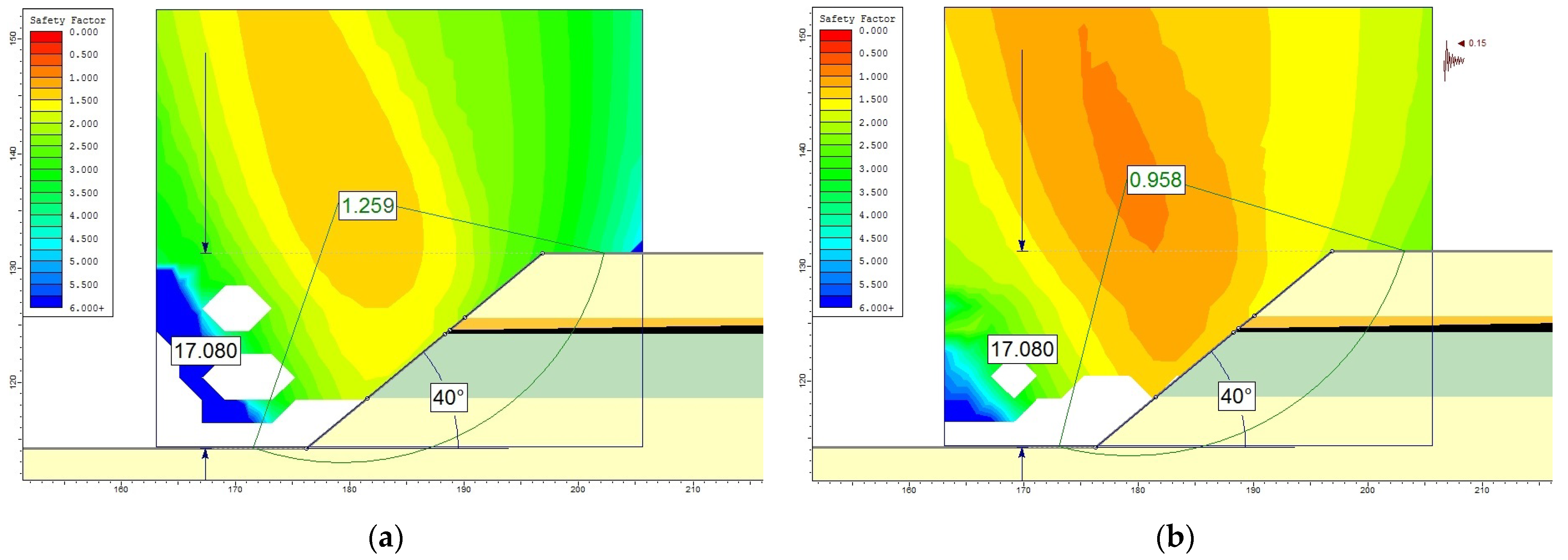
| T3 (Figure 10) | 17.08 | 40 | 1.294 | 1.353 | 1.259 | 1.010 | 1.045 | 0.958 | |
| Peșteana North interior waste dump slopes | |||||||||
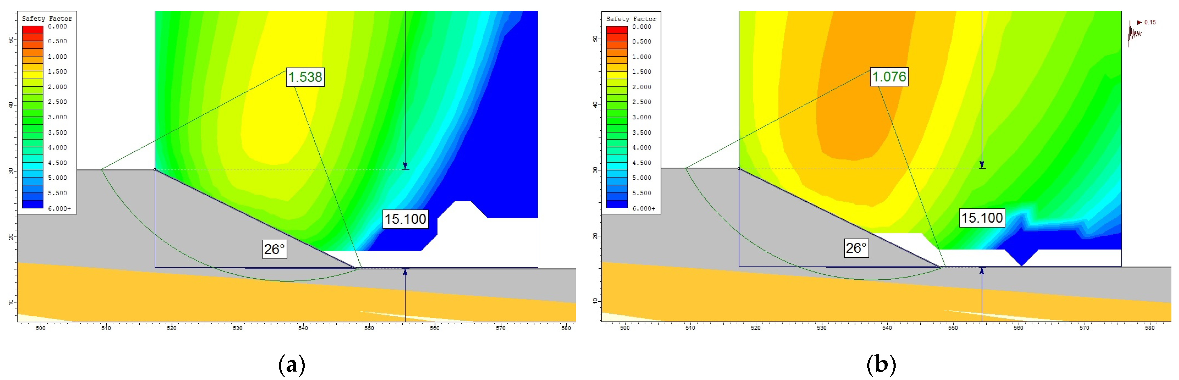
| 1′-1′ | TH2 (Figure 11) | 15.10 | 26 | 1.554 | 1.683 | 1.538 | 1.105 | 1.191 | 1.076 |
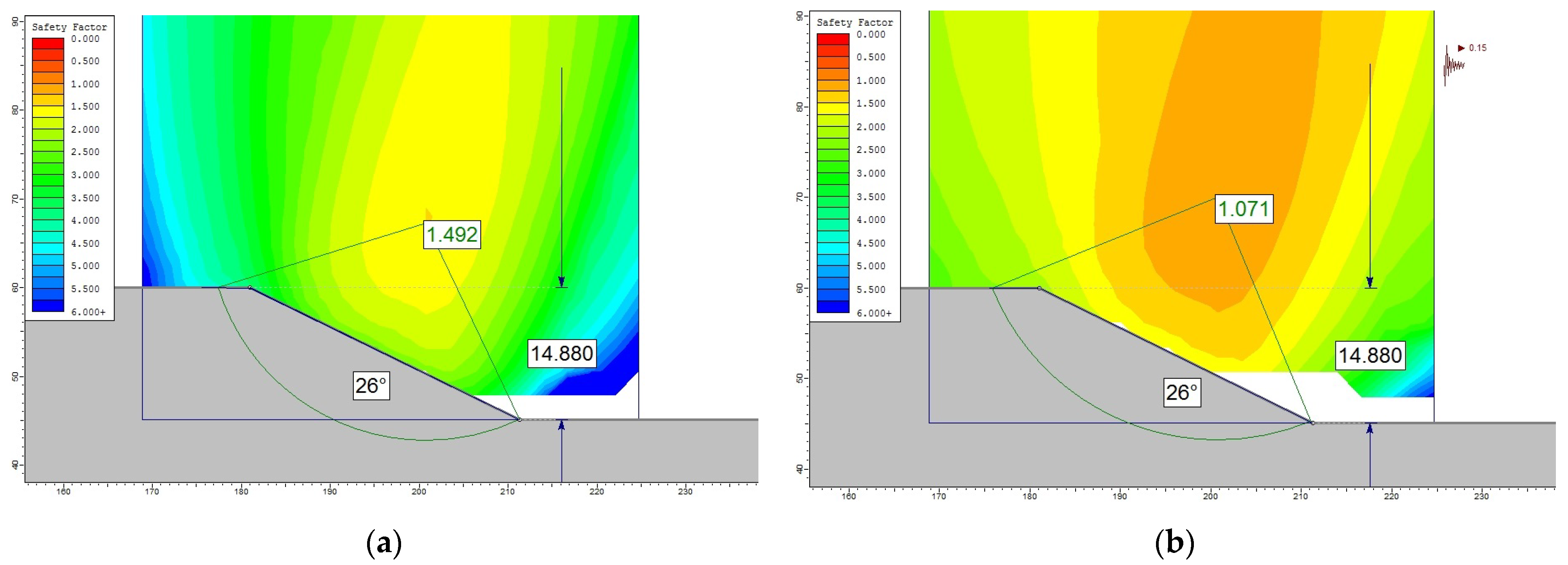
| TH4 (Figure 12) | 14.88 | 26 | 1.531 | 1.666 | 1.492 | 1.100 | 1.184 | 1.071 | |
| Geometric Element | Open Pit |
| Development of the working fronts (cross section) (m) | 633.27 |
| Height of the general slope (m) | 153.41 |
| Number of steps | 6 |
| General slope angle (°) | 13 |
| Height of the steps (m) | 20.00–30.00 |
| Berms width (m) | 61.10–116.66 * |
| Slope angle of individual steps (°) | 42–53 |
| Geometric Element | Internal Waste Dump |
| Development of the working fronts (cross section) (m) | 1191.23 |
| Height of the general slope (m) | 107 |
| Number of steps | 7 |
| General slope angle (°) | 5 |
| Height of the steps (m) | 9–20 |
| Berms width (m) | 141.40–261.38 ** |
| Slope angle of individual steps (°) | 28–49 |
| The Nature of Rocks from the Analysis Sections | γvnat [kN/m3] | cnat [kN/m2] | φnat [°] | |
|---|---|---|---|---|
 | Sandy clays (steps T1–T3) | 22.00 | 25.00 | 20.00 |
 | Clayey sands (intercalation in step T2) | 21.00 | 15.00 | 16.00 |
 | Coal clay (on top of layer X, between the banks of layer X, layers X and XII and as discontinuity of layer XII) | 18.00 | 33.25 | 28.00 |
 | Lignite (layers V–X and XII) | 13.40 | 200.00 | 35.00 |
 | Compact clay (on top of the pressurized aquifer, direct foundation of the internal waste dump) | 19.00 | 52.00 | 30.00 |
 | Mixture of waste rocks | 18.50 | 20.75 | 21.00 |
| Section | Individual Step | Height h [m] | Slope Angle α [°] | Stability Factor, Fs | |||||
|---|---|---|---|---|---|---|---|---|---|
| Initial Conditions | With Seismic Load (ag = 0.15 g) | ||||||||
| Fellenius | Bishop | Janbu | Fellenius | Bishop | Janbu | ||||
| Jilț North open pit slopes | |||||||||
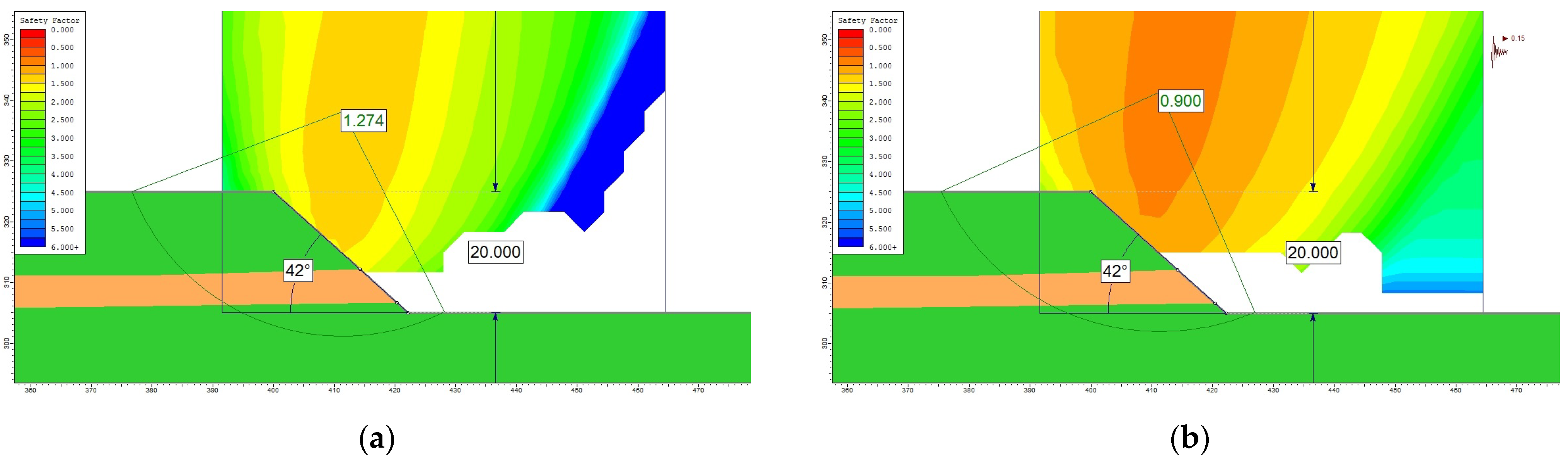
| 2-2 | T2 (Figure 15) | 20.00 | 42 | 1.300 | 1.408 | 1.274 | 0.938 | 1.000 | 0.900 |
| T5 (Figure 16) | 30.00 | 53 | 1.236 | 1.232 | 1.157 | 1.039 | 1.017 | 0.886 | |
| Jilț North interior waste dump slopes | |||||||||
| 2′-2′ | TH2 (Figure 17) | 18.00 | 40 | 1.149 | 1.224 | 1.113 | 0.886 | 0.929 | 0.855 |
| TH3 (Figure 18) | 20.00 | 38 | 1.393 | 1.532 | 1.382 | 1.015 | 1.095 | 0.982 | |
| Geometric Element | Open Pit | |
| Development of the working fronts (cross section) (m) | 400.03 | |
| Height of the general slope (m) | 90.00 | |
| Number of steps | 14 | |
| General slope angle (°) | 13 | |
| Height of the steps (m) | T1–T13 | 5.00 |
| T14 | 25.00 | |
| Berms width (m) | T1–T13 | 14.93 |
| T14 | 101.23 | |
| Slope angle of individual steps (°) | T1–T13 | 45 |
| T14 | 40 | |
| Geometric Element | Internal Waste Dump | |
| Development of the working fronts (cross section) (m) | 1049.99 | |
| Height of the general slope (m) | 98.50 | |
| Number of steps | 6 | |
| General slope angle (°) | 5 | |
| Height of the steps (m) | 10.00–16.50 | |
| Berms width (m) | 150.00–257.50 | |
| Slope angle of individual steps (°) | 18–45 | |
| The Nature of Rocks from the Analysis Sections | γvnat [kN/m3] | cnat [kN/m2] | φnat [°] | |
|---|---|---|---|---|
 | Yellow-brown clay (Alunu open pit) | 17.82 | 22.00 | 15.00 |
 | Lignite (layer 4 *) (Alunu open pit) | 11.80 | 30.00 | 19.00 |
 | Lignite layers (2 * and 3 *) (Alunu open pit) | 11.80 | 70.00 | 26.50 |
 | Sandy marl (Alunu open pit) | 18.50 | 32.00 | 20.50 |
 | Lignite layers (I, IIinf, IIsup, III, IV and 1 *) (Alunu open pit) | 11.80 | 110.00 | 30.00 |
 | Compacted sandy marl (Alunu open pit) | 19.11 | 45.00 | 21.00 |
 | Mixture of waste rocks (West Berbești internal dump) | 18.27 | 21.00 | 21.50 |
 | Rocks from the foundation of the West Berbești dump | 19.33 | 45.00 | 21.00 |
| Section | Individual Step/Steps System | Height h [m] | Slope Angle α [°] | Stability Factor, Fs | |||||
|---|---|---|---|---|---|---|---|---|---|
| Initial Conditions | With Seismic Load (ag = 0.20 g) | ||||||||
| Fellenius | Bishop | Janbu | Fellenius | Bishop | Janbu | ||||
| Alunu open pit slopes | |||||||||
| 3-3 | T2 (Figure 21) | 5.00 | 45 | 2.187 | 2.285 | 2.160 | 1.589 | 1.593 | 1.572 |
| T1–T8 (Figure 22) | 40.00 | 15 | 1.548 | 1.643 | 1.529 | 0.820 | 0.873 | 0.808 | |
| West Berbești interior waste dump slopes | |||||||||
| 3′-3′ | TH1 (Figure 23) | 13.50 | 28 | 1.646 | 1.731 | 1.612 | 1.123 | 1.181 | 1.082 |
| TH2 (Figure 24) | 15.00 | 45 | 1.307 | 1.371 | 1.292 | 0.912 | 0.948 | 0.873 | |
Disclaimer/Publisher’s Note: The statements, opinions and data contained in all publications are solely those of the individual author(s) and contributor(s) and not of MDPI and/or the editor(s). MDPI and/or the editor(s) disclaim responsibility for any injury to people or property resulting from any ideas, methods, instructions or products referred to in the content. |
© 2024 by the authors. Licensee MDPI, Basel, Switzerland. This article is an open access article distributed under the terms and conditions of the Creative Commons Attribution (CC BY) license (https://creativecommons.org/licenses/by/4.0/).
Share and Cite
Faur, F.; Apostu, I.-M.; Lazăr, M. Reassessment of the Stability Conditions in the Lignite Open Pits of Oltenia (Romania) in Relation to the New Local Seismic Context as an Imperative for Sustainable Mining. Sustainability 2024, 16, 1384. https://doi.org/10.3390/su16041384
Faur F, Apostu I-M, Lazăr M. Reassessment of the Stability Conditions in the Lignite Open Pits of Oltenia (Romania) in Relation to the New Local Seismic Context as an Imperative for Sustainable Mining. Sustainability. 2024; 16(4):1384. https://doi.org/10.3390/su16041384
Chicago/Turabian StyleFaur, Florin, Izabela-Maria Apostu, and Maria Lazăr. 2024. "Reassessment of the Stability Conditions in the Lignite Open Pits of Oltenia (Romania) in Relation to the New Local Seismic Context as an Imperative for Sustainable Mining" Sustainability 16, no. 4: 1384. https://doi.org/10.3390/su16041384