Last Updated on March 16, 2024
Even though lot of MEMS Microphone available in the market an easy and affordable way to transduce sound signal into electrical signal (Audio Signal) are implementing Electret or Carbon Microphone in Circuit. When we use these Microphones we can get direct Analog audio output and also better directional Characteristics.
Electret Mic
As we know Electret Microphone is a type of electrostatic capacitor based microphone and it requires DC potential for its operation and a DC blocking Capacitor at its Electrical Audio output pin, we designed a few components preamplifier circuit for Electret Microphone. The following Circuit Contains two BC549 NPN Transistors both are Configured in Common emitter configuration. Q2 transistor Stabilized to give half the DC input supply as Output so we can get maximum peak variations in output Audio signal.
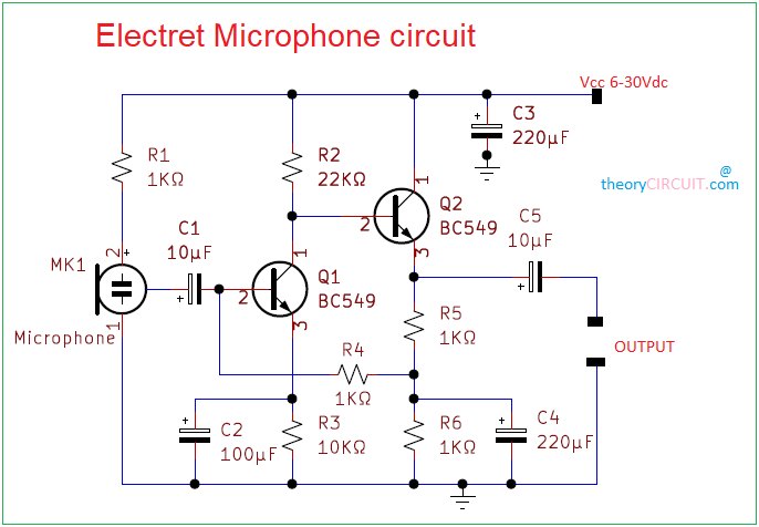
This simple Electret Microphone Circuit designed to operate using 6 volt to 30 volt DC supply but using 12V DC gives better output performance. If you are sing two terminal Electret Microphone then you can connect +Ve terminal of C1 Capacitor to +Ve terminal of Electret Mic along with R1. Here C1 Capacitor blocks DC from mic and gives low distortion audio to the base terminal of Q1. Decoupling Capacitor C2 at the emitter terminal of Q1 makes output gain high then Q2 transistor gives maximum level output through emitter terminal. C4 Capacitor grounds noise signal at the output. So we get very low noise output Audio Signal.
Carbon Microphone Preamplifier Circuit
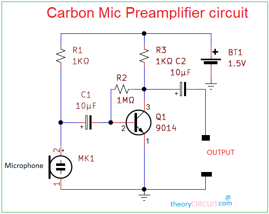
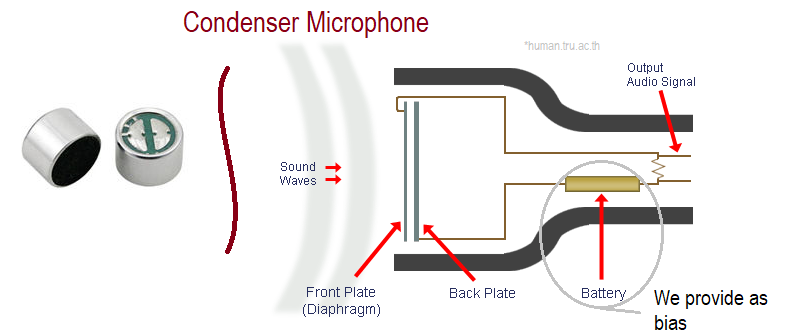
Handheld microphone most of the time utilize Carbon Mic as a sensor, as we know Carbon Mic will have Fixed electrode, Carbon granules and diaphragm. When the sound or acoustic wave hits the diaphragm it will vibrates the Carbon granules and fixed electrode converts its vibration into electrical audio signal here amplitude of audio signal is depends on the bias applied to the mic. To get better noise free audio output we need a Carbon Mic preamplifier circuit. In the given circuit Transistor Q1 Configured in Common emitter Collector to base bias. C1 and C2 Capacitors blocks the DC bias and allows only Audio signal hence we get noise and distortion free audio output from this preamplifier circuit. We can power this circuit from 1.5V to 6V.
BOM
| S.No | Designator | Value | Quantity |
| 1 | Microphone M1 | 2 | |
| 2 | R1,R5,R6 | 1KΩ | 3 |
| R2 | 22KΩ | 1 | |
| R3 | 10KΩ | 1 | |
| 3 | C1,C5 | 10μF | 2 |
| C2 | 100μF | 1 | |
| C3,C4 | 220μF | 2 | |
| 4 | Q1,Q2 | BC 549C | 2 |
| 5 | R1,R3 | 1KΩ | 2 |
| R2 | 1MΩ | 1 | |
| 6 | C1,C2 | 10μF | 2 |
| 7 | Q1 | 9014 | 1 |
| 8 | Battery | 1.5V | 1 |
Pinout

Can I substitute a BC547B for the BC549s in this schematic? If so what other changes should I make?
better. Hih gain tansistors can be cause problems