impact / impact e wall mounted units technical manual - Heronhill Air ...
impact / impact e wall mounted units technical manual - Heronhill Air ...
impact / impact e wall mounted units technical manual - Heronhill Air ...

Create successful ePaper yourself
Turn your PDF publications into a flip-book with our unique Google optimized e-Paper software.
IMPACT / IMPACT E WALL MOUNTED UNITS<br />
TECHNICAL MANUAL<br />
53799173-05
INDEX<br />
CONTENTS<br />
PAGE<br />
GENERAL. 2<br />
PART NUMBERS, DIMENSIONS & WEIGHTS, FEATURES & ACCESSORIES, UNIT<br />
COMBINATIONS.<br />
3<br />
SYSTEMS & PERFORMANCE, ELECTRICAL HEATING, AIR FLOWS. 4<br />
SOUND POWER AND SOUND PRESSURE LEVELS, ELECTRICAL DATA. 5 – 6<br />
ELECTIRAL LOADS. 6 - 7<br />
UNIT INSTALLATION. 7 - 9<br />
APLLICATION, RESTRICTORS. 10 - 11<br />
PIPE CONNECTIONS. 12<br />
ELECTRICAL CONNECTIONS. 13<br />
E REMOTE CONTROLLER. 14<br />
WIRING DIAGRAMS. 15 - 18<br />
EXPLODED VIEW, COMPONENT IDENTIFICATION. 19<br />
GENERAL<br />
1. TEV Ltd recommend that personnel working on this equipment be skilled and fully conversant with<br />
the appropriate <strong>Air</strong> Conditioning, Refrigeration and Electrical practices and have sound knowledge<br />
of current Industrial Safe Working practices.<br />
2. The <strong>impact</strong> <strong>wall</strong> <strong>mounted</strong> range of split systems comprises of 537 series <strong>impact</strong> <strong>wall</strong> <strong>mounted</strong><br />
indoor <strong>units</strong>, 550 series condensing <strong>units</strong> and 551 series heat pump outdoor <strong>units</strong>, or 542 series<br />
ducted condensing <strong>units</strong> and 543 series electronic ducted heat pump <strong>units</strong>. By choosing<br />
appropriate combinations the installer can provide:<br />
a. <strong>Air</strong> conditioners with a cooling range of 1.6 – 9.9 kW.<br />
b. Heatpump systems with a cooling range of 2.0 – 8.6kW, and a heating range of<br />
1.9 – 9.4kW with an outdoor temperature of minus 1°C.<br />
3. These <strong>units</strong> contain live electrical components, moving parts and refrigerant under pressure.<br />
Always site out of reach of children and protect from vandalism.<br />
4. The data plate only gives information for the <strong>impact</strong> unit. For system details add input power and<br />
current of indoor and outdoor unit, including any heater load.<br />
2/20<br />
53799173-05
PART NUMBERS<br />
Electromechanical Models IMPACT 20 IMPACT 40 IMPACT 60<br />
Part Number 53700001 53700002 53700003<br />
Electronic Models IMPACT 20E IMPACT 40E IMPACT 60E<br />
Part Number 53700011 53700012 53700013<br />
DIMENSIONS AND WEIGHTS (for dimensions, weights and sizes of outdoor <strong>units</strong> refer to outdoor<br />
unit <strong>technical</strong> <strong>manual</strong>)<br />
IMPACT INDOOR UNITS (unpacked)<br />
Model<br />
IMPACT<br />
20(E) 40(E) 60(E)<br />
HEIGHT mm 490 490 490<br />
WIDTH mm 550 850 1150<br />
DEPTH mm 204 204 204<br />
WEIGHT kg 14 18 24<br />
IMPACT INDOOR UNITS (packed)<br />
Model<br />
IMPACT<br />
20(E) 40(E) 60(E)<br />
HEIGHT mm 616 616 616<br />
WIDTH mm 720 1020 1320<br />
DEPTH mm 290 290 290<br />
WEIGHT kg 16 20 27<br />
FEATURES / ACCESSORIES<br />
IMPACT IMPACT (E)<br />
Adjustable air deflectors STD STD<br />
De-ice thermostat * STD<br />
Electric heating * *<br />
Electromechanical thermostat STD ---<br />
3 fan speeds STD STD<br />
Remote hard wired control --- STD<br />
Remote infrared control --- STD<br />
Network / Multisplit control --- STD<br />
Programmable timer * STD<br />
Condensate pump * *<br />
Long life washable filter STD STD<br />
Flame retardant material STD STD<br />
High or low level mounting STD STD<br />
KEY: * = factory/site option STD = standard --- = not available<br />
UNIT COMBINATIONS<br />
AIR CONDITIONING SYSTEMS<br />
HEAT PUMP SYSTEMS<br />
IMPACT MCU+ / DCU+ IMPACT MHPUE / DHPUE<br />
20 (E) 15 20 (E) 15<br />
40 (E) 30 / 40 40 (E) 30<br />
60 (E) 40 / 60 60 (E) 50<br />
3/20<br />
53799173-05
AIR CONDITIONER SYSTEMS AND PERFORMANCE (kw)<br />
UK CONDITIONS<br />
ROOM 21°C/15°C<br />
AMBIENT 27°C/19°C<br />
NEMA (EUROVENT)<br />
ROOM 27°C/19°C<br />
AMB 35°C/24°C<br />
TROPICAL<br />
ROOM 29°C/19°C<br />
AMB 46°C/24°C<br />
IMPACT + MCU+<br />
or DCU+<br />
MIN SPEED EVAP MAX SPEED EVAP MAX SPEED EVAP MAX SPEED EVAP<br />
TOTAL SHR SENS TOTAL SHR SENS TOTAL SHR SENS TOTAL SHR SENS<br />
20(E) + 15 1.4 0.71 1.1 1.9 0.77 1.5 2.1 0.78 1.6 1.6 0.98 1.6<br />
40(E) + 30 2.3 0.77 1.8 3.1 0.83 2.5 3.4 0.84 2.9 2.9 0.96 2.8<br />
40(E) + 40 2.7 0.74 2.0 3.6 0.78 2.8 4.0 0.78 3.1 3.2 0.98 3.1<br />
60(E) + 40 3.0 0.78 2.3 3.9 0.88 3.5 4.4 0.86 3.8 3.7 0.99 3.7<br />
60(E) + 60 3.7 0.74 2.7 5.1 0.80 4.1 5.4 0.81 4.4 4.4 0.98 4.3<br />
For MED speed duties, interpolate between MIN speed and MAX speed duties.<br />
Rating conditions are to BS2852: Part 1: 1982: UK condition C; NEMA condition A; Tropical condition B.<br />
HEAT PUMP PERFORMANCE<br />
1. Cooling, (MAX speed outdoor unit fan). (kW)<br />
UK CONDITIONS<br />
NEMA (EUROVENT)<br />
ROOM 21°C/15°C AMBIENT 27°C/19°C R27°C/19°C A35°C/24°C<br />
MIN SPEED INDOOR FAN MAX SPEED INDOOR FAN MAX SPEED INDOOR FAN<br />
IMPACT / MHPUE or DHPUE TOTAL SHR SENS TOTAL SHR SENS TOTAL SHR SENS<br />
20E - 15 1.2 0.75 0.9 1.7 0.81 1.4 2.0 0.78 1.6<br />
40E – 30 2.2 0.78 1.7 3.0 0.83 2.5 3.3 0.85 2.8<br />
60E - 50 3.5 0.72 2.6 4.8 0.82 3.9 5.3 0.81 4.3<br />
2. Heating, (room 20°C / 12°C, outdoor unit fan at MAX speed). (kW)<br />
HEATING OUTPUT AT 7°C AMBIENT HEATING OUTPUT AT -1°C AMBIENT<br />
MAX SPEED INDOOR FAN<br />
MAX SPEED INDOOR FAN<br />
IMPACT / MHPUE or DHPUE kW COP kW COP<br />
20E – 15 2.3 2.23 1.9 2.00<br />
40E – 30 4.0 2.78 3.1 2.30<br />
60E - 50 5.4 2.60 4.3 2.20<br />
OPTIONAL ELECTRIC HEATING<br />
IMPACT<br />
at 230V 50Hz<br />
(kW)<br />
at 240V 50Hz<br />
(kW)<br />
20(E) 0.7 0.8<br />
40(E) 1.4 1.5<br />
60(E) 2.1 2.25<br />
80(E) 2.75 3.0<br />
100(E) 3.2 3.5<br />
AIRFLOWS IMPACT UNITS<br />
MIN Speed MED Speed MAX Speed<br />
IMPACT CFM M³/S CFM M³/S CFM M³/S<br />
20(E) 125 0.06 170 0.08 210 0.10<br />
40(E) 275 0.13 345 0.16 420 0.20<br />
60(E) 360 0.17 440 0.21 645 0.30<br />
4/20<br />
53799173-05
SOUND POWER AND SOUND PRESSURE LEVELS<br />
IMPACT UNITS<br />
SOUND POWER LEVELS<br />
Frequency Hz<br />
5/20<br />
SOUND PRESSURE LEVELS<br />
MODEL SPEED 125 250 500 1K 2K 4K dBA dBA NC<br />
20 Min 42.1 48.6 52.2 47.4 40.7 34.8 52.1 31.6 26<br />
Med 45.5 51.3 54.6 51.8 45.3 39.1 55.6 35.1 30<br />
Max 48.3 53.9 57.2 55.2 48.8 42.9 58.7 38.2 33<br />
40 Min 45.9 51.4 53.3 51.3 46.9 44.6 55.6 35.1 30<br />
Med 47.5 53.1 55.4 53.5 48.9 45.8 57.6 37.1 32<br />
Max 50.7 55.6 58.0 56.6 51.9 48.0 60.4 39.9 35<br />
60 Min 56.4 51.1 52.8 50.2 47.2 42.4 55.2 34.7 27<br />
Med 56.6 53.0 55.4 52.9 48.6 43.6 57.3 36.8 31<br />
Max 58.0 57.8 60.3 58.9 53.7 48.9 62.6 42.1 37<br />
Sound Power Levels were obtained in full conformity with BS 4196: Part 5: 1981. Quantities are shown in dB<br />
with a standard reference of 1 pW.<br />
Sound Pressure Levels are dB relative to 2 x 10 -5 N/m 2 and are calculated from the results under anechoic<br />
conditions and are quoted as an average of all points on a hemisphere of a radius of 3m away from the<br />
centre of the unit.<br />
ELECTRICAL DATA<br />
R407C AIR CONDITIONING SYSTEMS (MCU+)<br />
MODEL<br />
COMBINATION<br />
Single Phase Supply 230Volts - 50Hz<br />
Three Phase Supply 400Volts - 50Hz<br />
INPUT FULL LOAD AMPS<br />
SYSTEM<br />
INPUT FULL LOAD AMPS<br />
SYSTEM<br />
MAX.<br />
MAX.<br />
STARTING<br />
Cooling Heating Cooling Heating CURRENT Cooling Heating Cooling Heating STARTING<br />
CURRENT<br />
IMPACT + MCU+ kW kW AMPS AMPS AMPS kW kW A/PH A/PH* A/PH<br />
20(E) + 15 0.9 0.9 6.4 4.0 23 -- -- -- -- --<br />
40(E) + 30 1.4 1.7 8.7 7.6 37 1.4 1.7 4.5 7.6 19<br />
40(E) + 40 1.6 1.7 10.8 7.6 51 1.6 1.7 5.7 7.6 23<br />
60(E) + 40 1.6 2.5 10.9 11.1 51 1.6 2.5 5.8 11.1 23<br />
60(E) + 60 2.5 2.5 10.2 10.8 62 2.5 2.5 4.6 10.8 33<br />
R407C AIR CONDITIONING SYSTEMS (DCU+)<br />
MODEL<br />
COMBINATION<br />
Single Phase Supply 230Volts - 50Hz<br />
Three Phase Supply 400Volts - 50Hz<br />
INPUT FULL LOAD AMPS<br />
SYSTEM<br />
INPUT FULL LOAD AMPS<br />
SYSTEM<br />
MAX.<br />
MAX.<br />
STARTING<br />
Cooling Heating Cooling Heating CURRENT Cooling Heating Cooling Heating STARTING<br />
CURRENT<br />
IMPACT + DCU+ kW kW AMPS AMPS AMPS kW kW A/PH A/PH* A/PH<br />
20(E) + 15 1.3 0.9 6.0 4.0 25 -- -- -- -- --<br />
40(E) + 30 1.8 1.7 8.4 7.6 37 1.8 1.7 3.6 7.6 19<br />
40(E) + 40 2.3 1.7 10.6 7.6 51 2.3 1.7 4.8 7.6 24<br />
60(E) + 40 2.3 2.5 10.7 11.1 51 2.3 2.5 4.9 11.1 24<br />
60(E) + 60 3.1 2.5 14.3 11.1 61 3.1 2.5 6.0 11.1 26<br />
R407C HEAT PUMP SYSTEMS (MHPUE)<br />
MODEL<br />
COMBINATION<br />
STD.<br />
MODEL<br />
Single Phase Supply 230Volts - 50Hz<br />
Three Phase Supply 400Volts - 50Hz<br />
INPUT FULL LOAD AMPS SYSTEM INPUT FULL LOAD AMPS<br />
MAX.<br />
+ ELECT STD. + ELECT STARTING STD. + ELECT STD. + ELECT<br />
Heating MODEL Heating CURRENT MODEL Heating MODEL Heating<br />
SYSTEM<br />
MAX.<br />
STARTING<br />
CURRENT<br />
IMPACT + MHPUE kW kW AMPS AMPS AMPS kW kW A/PH A/PH* A/PH<br />
20(E) + 15 0.9 1.7 6.4 9.9 31 -- -- -- -- --<br />
40(E) + 30 1.4 3.0 8.7 15.7 42 1.4 3.0 4.5 11.5 26<br />
60(E) + 50 2.1 4.5 9.5 19.9 61 2.1 4.5 4.6 15.0 33<br />
* Max Phase<br />
53799173-05
R407C HEAT PUMP SYSTEMS (DHPUE)<br />
MODEL<br />
COMBINATION<br />
STD.<br />
MODEL<br />
Single Phase Supply 230Volts - 50Hz<br />
Three Phase Supply 400Volts - 50Hz<br />
INPUT FULL LOAD AMPS SYSTEM INPUT FULL LOAD AMPS<br />
MAX.<br />
+ ELECT STD. + ELECT STARTING STD. + ELECT STD. + ELECT<br />
Heating MODEL Heating CURRENT MODEL Heating MODEL Heating<br />
SYSTEM<br />
MAX.<br />
STARTING<br />
CURRENT<br />
IMPACT + DHPUE kW kW AMPS AMPS AMPS kW kW A/PH A/PH* A/PH<br />
20(E) + 15 1.3 2.2 4.6 8.1 23 -- -- -- -- --<br />
40(E) + 30 1.8 3.5 9.1 16.1 46 1.7 3.5 3.9 10.9 28<br />
60(E) + 50 2.5 5.0 11.7 22.1 65 2.5 5.0 5.3 15.7 38<br />
* Max Phase<br />
ELECTRICAL LOADS (230V 50Hz 1Ph, A or 400V 50Hz 3PhN, A/Ph)<br />
IMPACT<br />
20E 40E 60E<br />
FAN MOTOR 0.2 0.3 0.4<br />
ELECTRIC HEATER (AIR COND.) 3.5 7 10.4<br />
ELECTRIC HEATER (HEAT PUMPS) 3.5 7 10.4<br />
FUSES<br />
The system and its supply/interconnecting wiring must be protected by fuses, preferably High Rupture<br />
Current (HRC) motor rated types (EN60269) or miniature circuit breakers (EN60898) or local codes having<br />
similar time lag characteristics, that allow starting of the compressor yet still afford close overcurrent<br />
protection under running conditions. The ratings below are for HRC motor rated fuses.<br />
FUSES FOR SYSTEMS WITH SINGLE PHASE (230V) OUTDOOR UNITS (A)<br />
IMPACT (E)<br />
MCU+ or 20 40 60<br />
DCU+ S H S H S H<br />
15 16 16<br />
30 16 16<br />
40 20 20 20 20<br />
60 20 20<br />
MHPUE or<br />
DHPUE<br />
S H S H S H<br />
30 10 16<br />
50 20 20<br />
S = Standard H = Heaters<br />
FUSES FOR SYSTEMS WITH THREE PHASE (400V) OUTDOOR UNITS (A/Ph)<br />
MCU+ or<br />
IMPACT (E)<br />
40 60<br />
DCU+ S H S H<br />
30 10 10<br />
40 10 10 16 16<br />
60 10 16<br />
MHPUE or<br />
DHPUE<br />
S H S H<br />
30 10 16<br />
50 10 16<br />
S = Standard H = Heaters<br />
6/20<br />
53799173-05
SEPARATE SUPPLIES TO ELECTRONIC INDOOR AND OUTDOOR UNITS (A)<br />
HEAT PUMP SYSTEMS ONLY<br />
It is recommended that systems using electronic indoor AND outdoor <strong>units</strong> should be independently fused.<br />
NOTE THAT THESE SUPPLIES MUST BE TAKEN FROM THE SAME PHASE<br />
IMPACT E<br />
20 40 60<br />
1Ph Cool Only 5 5 5<br />
1Ph Cool and Heat 5 10 10<br />
OUTDOOR UNIT<br />
MHPUE 15<br />
DHPUE 15<br />
MHPUE 30<br />
DHPUE 30<br />
MHPUE 50<br />
DHPUE 50<br />
1Ph (A) 10 16 20<br />
3Ph (A/Ph) --- 10 10<br />
IMPACT (E) WALL MOUNTED UNIT INSTALLATION<br />
The installer supplies:<br />
Unpacking<br />
• 4 off M6 (or equivalent strength) Rawlbolt shields, bolts and washers.<br />
• Fully insulated refrigeration pipework.<br />
• All mains wiring with suitable isolation; Interconnecting wires for indoor and outdoor <strong>units</strong>.<br />
• Condensate drain (minimum 10mm bore for gravity drain, 8mm bore for condensate pump<br />
drain).<br />
• Two spanners for securing the flare connectors.<br />
• A cross-headed screwdriver for releasing the end cover fasteners.<br />
• A 4 or 5mm Allen key for opening the outdoor/ducted unit valves (depending on valve type).<br />
• Method for securing solid sheathed cables if these are used.<br />
Carefully unfasten the banding and lift off the outer cardboard carton sleeve.<br />
The following are supplied:<br />
• IMPACT unit (in protective sleeve, held between two polystyrene end caps).<br />
• A cardboard sleeve containing two pipe assemblies complete with insulation and two cable<br />
glands suitable for flexible, p.v.c. sheathed cable.<br />
• A <strong>wall</strong>-mounting bracket also held between the two polystyrene end caps.<br />
• Envelope containing operating instructions to be left with the end user.<br />
• IMPACT E models also have an electronic remote control assembly incorporating the infrared<br />
controller, <strong>wall</strong> mounting bracket, two screws and <strong>wall</strong> plugs and a battery.<br />
1 Remove and place to one side the cardboard sleeve containing the two pipe<br />
assemblies, (and remote control assembly on IMPACT E models).<br />
2 Lift the IMPACT unit from the inner cardboard sleeve complete with the two<br />
polystyrene end caps; (this will require 2 people for sizes 60 to 100).<br />
3 Remove the <strong>wall</strong>-mounting bracket and carefully remove the two polystyrene end<br />
caps and the protective sleeve from the IMPACT unit.<br />
4 Remove both end covers by removing the self-tapping screws, one on each end<br />
trim. By pulling the end covers sharply they can be removed from the backpanel<br />
and fascia.<br />
7/20<br />
53799173-05
Chassis Mounting<br />
NOTE:<br />
It is generally easier to fit kits prior to mounting the unit and connecting the pipework.<br />
It is essential to fit a heater kit at this stage if right hand side access will be limited<br />
to less than the unit width.<br />
.<br />
1 Ensure that the <strong>wall</strong> is flat and will support the operating weight of the unit, (see below)<br />
2 Ensure that sufficient access is left around the unit for future kit fitting, servicing and<br />
maintenance.<br />
INSTALLATION AND SERVICE ACCESS<br />
CEILING<br />
30mm<br />
minimum<br />
LEFT<br />
HAND<br />
WALL<br />
RIGHT<br />
HAND<br />
WALL<br />
To allow<br />
top box<br />
removal<br />
Model<br />
Weight<br />
kg<br />
Operating<br />
Weight<br />
kg<br />
20(E) 14 15<br />
40(E) 18 21<br />
60(E) 24 25<br />
*Includes all kits and refrigerant<br />
200mm<br />
minimum<br />
FLOOR<br />
(*Unless heaters fitted)<br />
200mm*<br />
minimum<br />
150mm<br />
minimum<br />
(screwdriver<br />
access)<br />
*Removal or replacement of heater elements requires a clearance at the right hand side equal to the<br />
length of the unit<br />
3 Mark out the two required top-hole centres as shown in Fig.<br />
2, (note that the top of the IMPACT unit will be<br />
approximately 100mm above the level of the hole<br />
centres). Drill to suit M6 Rawlbolt shields or equivalent<br />
strength fasteners. Secure the <strong>wall</strong>-mounting bracket to the<br />
upper two holes ensuring that it is level.<br />
4 Hang the unit on the two protrusions from the <strong>wall</strong> mounting<br />
bracket and, ensuring that the unit is level, mark out and drill<br />
the lower two holes and secure the unit to the <strong>wall</strong>.<br />
Model 20E 40E 60E<br />
A1 445 745 1045<br />
A2 395 695 995<br />
A3 345 645 945<br />
B 370 370 370<br />
C 340 340 340<br />
D 31 31 31<br />
E 29 29 29<br />
A1<br />
A2<br />
A3<br />
C<br />
B<br />
D<br />
E<br />
8/20<br />
53799173-05
Condensate Removal<br />
Condensate collects in a drip tray along the full length of the coil.<br />
An outlet pipe is provided at the rear left hand end of the tray for connection to a pipe for gravity drain.<br />
Slide the outlet pipe from the clip and exit the unit vertically through the hole in the backpanel or base tray.<br />
The drain stub has a 14mm o.d. barb and is supplied with connector and a short length of 6.35mm i.d. hose<br />
For connection to a 10-12mm i.d. flexible hose, remove the hose and connector supplied and connect<br />
directly to the stub.<br />
Ensure that the drain pipe is kept below the rim of the drip tray along its entire length.<br />
Once a gravity drain has been installed, check to ensure that the pipe is not kinked and that correct drainage<br />
occurs by slowly filling the drip tray with water.<br />
A condensate pump kit (incorporating overflow protection) can be fitted within the unit to enable a lift of up to<br />
5m.<br />
<strong>Air</strong> Deflection<br />
<strong>Air</strong> deflection is set by <strong>manual</strong>ly adjusting the vanes. The unit is supplied with front discharge but can be<br />
changed to top discharge as follows.<br />
1 Remove the filters.<br />
2 Remove the end covers.<br />
3 Using a screwdriver or thin bladed tool, release the three tabs at the bottom of the top box; these are<br />
directly below the centre and two end vertical vanes.<br />
4 Lift the top box assembly from the unit.<br />
5 By gently flexing the top box sides from the rear, transfer the deflector plate from the upper to the<br />
lower two fixing holes.<br />
6 Rotate the top box assembly and refit to give top discharge.<br />
TABS<br />
AIR<br />
AIR<br />
DEFLECTOR AS<br />
SUPPLIED FOR<br />
FRONT DISCHARGE<br />
MOVE DEFLECTOR<br />
TO ALTERNATIVE<br />
POSITION<br />
TURN TOP BOX<br />
THROUGH 180° AND<br />
SNAP IN TO SUIT<br />
TOP DISCHARGE<br />
9/20<br />
53799173-05
APPLICATION<br />
1 To maximise performance, pipe runs should be kept as short as possible, avoiding sharp bends.<br />
However, individual pipe runs to a maximum of 80m, including 20m lift, are permissible provided good<br />
refrigeration practice is followed.<br />
Published performance duties are based on 7.5m pipe runs. Correctly sized pipes for each installation,<br />
and fitting the correct expansion orifice (restrictor) will result in no significant loss of capacity on<br />
extended pipe runs.<br />
a) Pipe sizes are based on: -<br />
Minimum of 3.8 m/s (750 fpm) suction gas velocity for horizontal or downflow.<br />
Minimum of 7.6 m/s (1500 fpm) suction gas velocity for upflow.<br />
Maximum of 15.2 m/s (3000 fpm) suction gas.<br />
b) Where vertical risers exceed 3m, oil traps must be formed in the pipe. This will help ensure that oil<br />
returns to<br />
the compressor. Typically fit an oil trap every 3m with a trap at the bottom of the riser.<br />
2 Add 25 grams of polyolester (POE) oil for every 350 grams of charge added to systems with pipe runs<br />
exceeding 25m, up to a maximum of 300 grams; preferably by slowly pumping into the suction side with<br />
the unit running, after charging the system.<br />
3 The maximum pipe lengths to be used for each pipe size and outdoor unit are shown in the table below.<br />
Use of these sizes and lengths is recommended in order to achieve optimum system performance.<br />
4 In calculating equivalent lengths of pipe runs, the effect of bends and fittings must be taken into<br />
account. The table below covers the fittings most likely to be encountered in this type of installation.<br />
The equivalent lengths of all the fittings in a particular pipe run must be added together and the total<br />
added to the actual length of pipe in the run, in order to calculate the total equivalent length.<br />
FITTING LOSSES, in equivalent straight lengths of pipe (metres).<br />
Pipe Size (outside diameter in inches)<br />
Fitting 3/8 1/2 5/8 3/4 7/8 1-1/8<br />
45° Bend 0.12 0.15 0.18 0.21 0.24 0.3<br />
90° Bend R/d = 1 0.37 0.43 0.49 0.55 0.61 0.79<br />
90° Bend R/d = 1.5 0.24 0.27 0.30 0.37 0.43 0.52<br />
180° Bend C/d = 0.73 0.91 1.10 1.28 1.46 1.83<br />
180° Bend C/d = 0.46 0.55 0.64 0.76 0.85 1.07<br />
90° Elbow 0.67 0.85 1.04 1.25 1.46 1.89<br />
R = Radius of bend d = Diameter of tube C = Centres of<br />
5 Use the shortest possible route, avoiding sharp bends.<br />
6 Fully insulate both the suction and expansion lines, including the expansion device, since both lines<br />
may sweat.<br />
10/20<br />
53799173-05
RESTRICTOR MATCHES<br />
Outdoor <strong>units</strong> are supplied with cooling restrictors fitted in the expansion assembly; refer to the following<br />
tables for any restrictor changes. Those ticked do not require a change of restrictor.<br />
Where appropriate, the alternative cooling or heating restrictor is supplied with either the indoor or the<br />
outdoor unit<br />
SYSTEM<br />
MATCH<br />
PIPE CONNS MAXIMUM PIPE RUNS (m) COOLING RESTRICTOR<br />
MCU+<br />
DCU+<br />
SUCTION<br />
EXPANSION<br />
SUC EXP<br />
UK +<br />
3/8 1/2 5/8 3/4 7/8 11/8<br />
UK NEMA<br />
3/8 1/2 5/8<br />
NEMA<br />
CHARGE TO<br />
ADD<br />
(for 7.5m) (1)<br />
UK<br />
(g)<br />
NEMA<br />
(g)<br />
IMPACT 20 3/8 3/8<br />
MCU+15/<br />
DCU+ 15<br />
3/8 3/8<br />
IMPACT 40 1/2 3/8<br />
MCU+30/<br />
DCU+ 30<br />
1/2 3/8<br />
IMPACT 40 1/2 3/8<br />
MCU+40/<br />
DCU+ 40<br />
1/2 3/8<br />
IMPACT 60 5/8 3/8<br />
MCU+40/<br />
DCU+ 40<br />
1/2 3/8<br />
IMPACT 60 5/8 3/8<br />
MCU+60/<br />
DCU+ 60<br />
5/8 3/8<br />
7.5 30 50 50 033 035 032 200 230<br />
15 50 80 50 80 040 042 039 0 60<br />
10 36 80 7.5 80 042 044 041 140 240<br />
10 36 80 7.5 80 042 044 043 200 300<br />
14 36 80 7.5 50 80 051 053 050 0 635<br />
D<br />
Restrictor / Orifice / Düse<br />
HEAT PUMP SYSTEMS (ALL CONDITIONS)<br />
Heat pumps are supplied with a heating restrictor in an expansion assembly. This must be fitted<br />
close to the indoor unit in the expansion line, (smaller of two connections) arrows pointing in the<br />
direction of the outdoor unit.<br />
= NO RESTRICTOR CHANGE<br />
NEEDED<br />
Cooling restrictor Heat pump cooling conditions<br />
Heating restrictor<br />
MHPUE IMPACT Fitted to the<br />
outdoor unit<br />
UK<br />
CONDITIONS<br />
NEMA<br />
CONDITIONS<br />
fitted to the outdoor<br />
expansion assembly<br />
15 20 033 035 035<br />
30 40 040 042 039<br />
50 60 052 044<br />
Cooling restrictor Heat pump cooling conditions<br />
DHPUE IMPACT Fitted to the<br />
outdoor unit<br />
UK<br />
CONDITIONS<br />
NEMA<br />
CONDITIONS<br />
15 20 032 027<br />
30 40 039 037<br />
50 60 049 044<br />
DHPUE<br />
MHPUE<br />
E<br />
11/20<br />
53799173-05
PIPE CONNECTIONS<br />
IMPACT UNITS<br />
Pipework is terminated at the left hand side of the unit. Two pipe assemblies are supplied loose with flare nut<br />
connectors to enable pipe exit from either the top or bottom of the unit via knockouts. Rear pipe exit is<br />
possible with installer supplied pipework.<br />
Always use two spanners to secure the flare connections to avoid distorting and damaging the pipework.<br />
Pipe flare connections (in inches) are;<br />
IMPACT Model 20(E) 40(E) 60(E)<br />
Expansion Pipe 3/8 3/8 3/8<br />
Suction Pipe 3/8 1/2 5/8<br />
1 If top or bottom pipe exit is required, remove the appropriate knockout in the backpanel flanges.<br />
2 Remove and retain the flare nuts from the coil, (the bonnets should be discarded).<br />
3 Screw the angled ends of the pipe extensions to the male connectors on the coil, ensuring that the<br />
straight ends extend through the knockout.<br />
For pipe exit through the rear of the unit, the installer must supply appropriately flared pipework.<br />
On heat pump systems the IMPACT unit needs to have an expansion assembly fitted; refer to<br />
the next section.<br />
4 Interconnecting pipework should be installed in accordance with good refrigeration practice.<br />
5 Final connection is made to the male flare connectors, either on the pipe extensions (for top or bottom<br />
entry) or directly onto the coil (for rear entry).<br />
6 Care should be taken to ensure that pipe flares are correctly formed and have undamaged seating<br />
surfaces. The use of a little oil on the flaring tool will help. DO NOT FORGET to fit the flare nut onto<br />
the pipe BEFORE flaring it.<br />
7 Make the flare connections to IMPACT using a little refrigeration oil on the mating surfaces. Always<br />
use two spanners in opposing directions to avoid twisting the pipework and damaging the coil<br />
connections.<br />
12/20<br />
53799173-05
ELECTRICAL CONNECTIONS<br />
1 Mains, control and interconnecting cables must be supplied and fitted by the installer.<br />
2 Installer wiring must be carried out in accordance with IEE regulations and local codes. Refer to the<br />
interconnecting wiring diagrams on pages 30 to 34.<br />
3 Mains supply cables must be size compatible with the recommended fuse for a given system (see<br />
pages 11 and 12).<br />
4 An all pole isolator switch should be positioned within easy reach of the indoor unit.<br />
5 The equipment must be earthed.<br />
6 Cable clamps for use with stranded cables are supplied in <strong>units</strong> 15 - 90 and should be used to secure<br />
all incoming/outgoing cables. Installers must supply a method of securing any solid sheathed cables.<br />
ELECTROMECHANICAL SYSTEMS<br />
Systems including an electromechanical unit require a supply to the condensing unit with connecting cables<br />
run to the indoor unit<br />
ELECTRONIC SYSTEMS (DCU+, DHPUE and MHPUE):<br />
It is recommended that systems with electronic indoor AND electronic outdoor <strong>units</strong> have a supply taken to<br />
the outdoor unit AND a separate supply taken to the indoor unit, which in many cases can be from a<br />
domestic 13 Amp socket, (see fuse ratings on pages 11 and 12), otherwise run a supply to the outdoor unit<br />
with connecting cables run to the indoor unit.<br />
Communication between the indoor and outdoor unit is via a two wire (max. 0.75mm 2 ) non-polarised<br />
connection (installer supplied), using cable type RS 485 or equivalent, (or two cores of 00526077, 4 core<br />
cable, available from TEV Ltd).<br />
The cable screen should be secured to ground (earth) at BOTH ends using the clamps provided. Do<br />
not attempt to run the communication in the spare cores of any power carrying cable.<br />
Whenever possible, the communication cable should be run separate from any mains cable.<br />
DATA PLATES<br />
Because of the ability to mix-match indoor and outdoor <strong>units</strong>, the data plate only gives information on<br />
outdoor <strong>units</strong>. To obtain the system details, input power and currents from indoor and outdoor <strong>units</strong> should<br />
be added together. Data plates show basic <strong>units</strong> with electric heater kit loads shown separately.<br />
FIRE LINK<br />
In order to automatically switch off the fan in the event of a fire, it is necessary to fit an external switch (240V,<br />
3A, closed to run, volt free contact) in series with the small black wire connected to the bottom terminal of the<br />
fuse. This switch should be operated by the building's fire alarm or BMS system.<br />
EVACUATING<br />
1. Connect a vacuum pump to the service ports on the outdoor unit valves and evacuate the<br />
interconnecting pipework and indoor unit to 1000 microns (1 Torr) or better and allow to be held for a<br />
minimum of 15 minutes.<br />
2. If NO additional refrigerant charge is required: Replace the caps on the service ports, (tighten to a<br />
torque of 25NM), and open the valves using a 4 or 5mm Allen key. On electronic <strong>units</strong>, REMOVE link<br />
JP6 identified by a white label, (otherwise the unit will always run at full speed).<br />
13/20<br />
53799173-05
ADDING REFRIGERANT<br />
1 If additional refrigerant charge is required:<br />
After evacuating the indoor unit and interconnecting pipework, open the valves using a 4 or 5mm Allen key. The<br />
high and low side pressures should equalise within a minute.<br />
2 Additional charge for all systems, including heat pumps, should be introduced with the system in the AIR<br />
CONDITIONING MODE.<br />
3 Additional charge should be introduced through the Schrader valve on the indoor unit or the service port on the<br />
suction service valve on the outdoor unit (see charging section overleaf to calculate the weight).<br />
4 DCUE, DHPUE and MHPUE are supplied with link JP6 fitted on the outdoor unit pcba; this allows additional<br />
charging and overrides alarms during the charging process. With both <strong>units</strong> powered, the DCUE, DHPUE or<br />
MHPUE fans will run at high speed and IMPACT E indoor fans will run at maximum speed. When JP6 is linked, the<br />
infrared handset is inoperative.<br />
NOTE: MCU+ <strong>units</strong> are fitted with head pressure control; before charging, isolate the unit and transfer the blue<br />
5 Ensure that the refrigerant being added is the same refrigerant that the system was originally charged with.<br />
6 If a <strong>manual</strong> HP cutout is fitted, ensure that the reset button is depressed.<br />
7 On DCUE, DHPUE and MHPUE models a random start delay of up to 1 minute occurs when mains is first applied.<br />
A 3 minute delay occurs between successive compressor operations on all systems incorporating DCUE, DHPUE<br />
and MHPUE <strong>units</strong>, or MCU(+) <strong>units</strong> fitted with a 3 minute timer kit.<br />
8 Run the system for a few minutes to allow it to stabilize. Where possible, charge to a sweat line on the evaporator.<br />
Typical suction pressures on short lines at UK conditions, with high speed evaporator fan, low speed condenser<br />
fan (commissioning speed for DCUE, DHPUE and MHPUE), should be; Electromechanical Comfort Systems<br />
approx. 4.4 bar (65 psig); Electronic Comfort Systems approx. 3.8 bar (55 psig); Heat Pump Systems approx. 4.0<br />
bar (58 psig).<br />
Care should be taken when the compressor is first started in the field to ensure that the system is not overcharged,<br />
in which case liquid return to the compressor could result.<br />
9 On DCUE, DHPUE and MHPUE <strong>units</strong>, once refrigerant has been added, REMOVE link JP6, identified by a white<br />
label (otherwise the unit will always run at full speed).<br />
10. On MCU+ <strong>units</strong>,return the blue wire from 1 to 4.<br />
WHEN INSTALLATION HAS BEEN COMPLETED - CHECK :-<br />
1. All pipe work and joints for leakage.<br />
2. All pipe work and fittings for insulation.<br />
3. All bolts are secure and that the fan rotates freely.<br />
CHARGING<br />
IMPACT WALL MOUNTED SYSTEMS - pipe runs below 7.5m.<br />
Each outdoor unit is charged with R22 or R407C as shown on page 18.<br />
Where additional refrigerant is needed this is shown on P18. Additional oil is not required.<br />
IMPACT WALL MOUNTED SYSTEMS - pipe runs over 7.5m.<br />
For pipe runs over 7.5m, extra refrigerant and oil must be added to the system by the installation engineer as<br />
shown on page 18 PLUS additional refrigerant and oil for each metre over 7.5m, based on the following:<br />
Expansion line size. 3/8 1/2 5/8<br />
Additional refrigerant (g/m) 16 30 48<br />
Additional oil<br />
25g per 350g of additional refrigerant to a<br />
maximum of 300g<br />
14/20<br />
53799173-05
INSTALLATION of the IMPACT E REMOTE CONTROLLER<br />
IMPACT E indoor <strong>units</strong> are supplied with a remote controller, <strong>wall</strong> mounting bracket, PP3 (9 volt) battery,<br />
screws and <strong>wall</strong> plugs.<br />
The controller either operates remotely by infrared signals, when the bracket may be used to park the<br />
controller for convenience, or may be hard wired to the unit (via the <strong>wall</strong> mounting bracket) in applications<br />
where infrared is inappropriate, e.g., high lighting level, no direct line of sight etc.<br />
1. Infrared operation<br />
Open the battery cover at the bottom rear of the controller by sliding out and hinging up, push the<br />
polarised connector onto the battery, slot into the controller and close the cover. The controller is now<br />
ready for operation as stated in the user handbook.<br />
For convenience, the <strong>wall</strong>-mounting bracket may be secured to a <strong>wall</strong> and used to park the controller.<br />
2<br />
SCREWDRIVER<br />
LOCKING CAM<br />
1<br />
2. Hard wired<br />
Use four core screened cable available from TEV Ltd in 100m drums, part number 00526117. The<br />
screen should be clamped to ground in the IMPACT E unit but NOT connected at the <strong>wall</strong> bracket end.<br />
NOTE: Great care should be taken to ensure that the wiring is correct, refer to the diagram<br />
below<br />
The cable should be connected prior to mounting the bracket, taking great care to ensure that the 4<br />
contact blades remain free to exert spring pressure on the handset terminals.<br />
Secure the bracket to the <strong>wall</strong> by drilling two 6mm diameter holes in the positions shown, inserting the<br />
<strong>wall</strong> plugs and securing with the two screws provided. Attach the controller to the bracket ensuring that it<br />
is pushed down firmly.<br />
If required, the controller may be locked into position by rotating the cam at the top of the bracket with a<br />
small screwdriver. The controller is now ready for operating as stated in the user handbook. The<br />
controller does not require a battery when this method is used.<br />
JP15<br />
4 +<br />
EARTH AT<br />
UNIT END<br />
ONLY<br />
CABLE<br />
ROUTING<br />
1<br />
-<br />
Ensure that cables<br />
are connected correctly<br />
ie 1 - 1<br />
2 - 2<br />
3 - 3<br />
4 - 4<br />
1 2 3 4<br />
BRACKET VIEWED<br />
FROM THE REAR<br />
Ensure cables are correctly connected<br />
ALTERNATIVE CABLE<br />
ROUTING<br />
15/20<br />
53799173-05
WIRING DIAGRAMS<br />
ELECTROMECHANICAL IMPACT<br />
ELECTRONIC IMPACT E<br />
16/20<br />
53799173-05
INTERCONNECTING WIRING DIAGRAMS<br />
20(E) - 60(E) + 1 Phase MCU+ 15 – 60 20E - 60E + 1 Phase MHPUE 15 - 50<br />
40(E) - 60(E) + 3 Phase MCU(+) 30 - 60 40E - 60E + 3 Phase MHPUE 30 - 50<br />
17/20<br />
53799173-05
IMPACT 20 –60 and 1 PHASE DCU+ 15 – 60<br />
IMPACT 20E – 60E and 1 PHASE DCU+/DHPUE 15 - 60<br />
+<br />
+<br />
+<br />
+<br />
+<br />
+ ++<br />
18/20<br />
53799173-05
IMPACT 40 - 60 and 3 Phase DCU+ 30 - 60<br />
IMPACT 40E - 60E and 3 Phase DCU+/DHPUE 30 – 60<br />
+ + + +<br />
19/20<br />
53799173-05
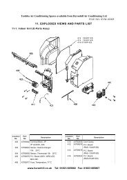
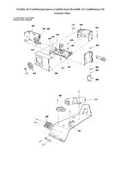
EXPLODED DIAGRAM OF IMPACT WITH COMPONENT IDENTIFICATION (IMPACT 40<br />
SHOWN)<br />
1 Top cover plate 15 Terminal assembly 29 Heater cut-out assembly<br />
2 Wall mounting bracket 16 Heater element 30 Electrics plate<br />
3 Back panel 17 Right hand end cover 31 Capacitor<br />
4 De-ice thermostat 18 Right hand door cover 32 Blank cover (electromechanical)<br />
5 Polystyrene scroll 19 Front cover 33 LED cover (electronic)<br />
6 Impeller 20 Filter 34 De-Ice sensor (electronic)<br />
7 Motor 21 Left hand end cover 35 Return air sensor (electronic)<br />
8 Drip tray assembly 22 Top box assembly 36 Condensate pump<br />
9 Power board (electronic) 23 Coil and header 37 Condensate pump sensor<br />
10 Thermostat (e/mechanical) 24 Extrusion 38 Condensate pump PCB<br />
11 Rotary switch (electromechanical) 25 Drip deflector Remote controller (not shown) shown)<br />
12 Right hand coil bracket 26 Left hand coil bracket 2 Amp fuse (not shown)<br />
13 Receiver board (electronic) 27 Rubber housing Heater relay (not shown)<br />
14 Rotary knob (Electromechanical) 28 Impeller spring<br />
20/20<br />
53799173-05