AQUA SYSTEMS - Heronhill Air Conditioning Ltd
AQUA SYSTEMS - Heronhill Air Conditioning Ltd
AQUA SYSTEMS - Heronhill Air Conditioning Ltd

You also want an ePaper? Increase the reach of your titles
YUMPU automatically turns print PDFs into web optimized ePapers that Google loves.
HYDRONIC AIR CONDITIONING<br />
IMI <strong>Air</strong> <strong>Conditioning</strong> <strong>Ltd</strong><br />
<strong>AQUA</strong> <strong>SYSTEMS</strong><br />
The natural solution for total environmental control<br />
A four pipe system,<br />
which utilises<br />
outdoor reverse<br />
cycle heat pumps.<br />
A four pipe system<br />
which utilises outdoor<br />
chillers and LPHW<br />
supply.<br />
A two pipe system,<br />
utilising outdoor<br />
reverse cycle heat<br />
pumps.<br />
<strong>AQUA</strong> MULTI is a two<br />
pipe system, utilising<br />
outdoor chillers.<br />
<strong>AQUA</strong> systems have a unique split coil design within each indoor unit. Each coil is split into two<br />
hydraulically balanced segments in the ratio of 70:30. 3 step capacity control of 30%, 70% and<br />
100% can be achieved by using simple, 2-port motorised valves, operated by the zone’s mini<br />
outstation. Variable fan speed provides further capacity control.<br />
■<br />
Flexible<br />
■<br />
Environmentally friendly<br />
modular approach<br />
All refrigerant in factory charged outdoor units.<br />
■<br />
BMS Controllable<br />
■<br />
Heat recovery<br />
■<br />
central controller and mini-out stations<br />
Energy efficient<br />
Performance may be enhanced by using an<br />
‘Aquavent’ air handling unit.<br />
Scroll compressors and plate heat exchangers.
Four Pipe Fan Coil System<br />
Intelligent 4-pipe FCU system served by 2 (or more) air to<br />
water reverse cycle heat pump chillers, suitable for multizone<br />
simultaneous heating / cooling applications.<br />
Four Pipe Fan Coil System<br />
4-pipe FCU system served by conventional air cooled<br />
chillers and separate boiler system Suitable for multi-zone<br />
simultaneous heating / cooling applications.<br />
■<br />
70/30 FCU split coil flexibility<br />
■<br />
70/30 FCU split coil flexibility<br />
■<br />
Communicating Trend control system<br />
■<br />
Communicating Trend control system<br />
■<br />
No pipe run/lift limitation<br />
■<br />
No pipe run/lift limitation<br />
■<br />
No limit to number of indoor units<br />
■<br />
No limit to number of indoor units<br />
■<br />
Heat recovery can be integrated into the system<br />
■<br />
Systems 12-500kW, 16 chiller models<br />
■<br />
<strong>AQUA</strong> 4 sizing software will ensure correct selection<br />
and orientation of indoor units<br />
PRIMARY HEAT<br />
PRIMARY COOL<br />
OUTDOOR UNIT<br />
OUTDOOR UNIT<br />
BOILER<br />
INDOOR UNIT ZONE 1<br />
Valve Open<br />
Valve Closed<br />
INDOOR UNIT ZONE 2<br />
CHILLER<br />
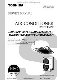
ALL HEATING<br />
Only requirements for heating exist in the building and both outdoor<br />
units provide hot water to all coil sections, as required.<br />
PRIMARY HEAT<br />
PRIMARY COOL<br />
INDOOR UNIT<br />
ZONE 1 Cooling<br />
OUTDOOR UNIT<br />
OUTDOOR UNIT<br />
INDOOR UNIT<br />
ZONE 1 Cooling<br />
Valve Open<br />
Valve Closed<br />
INDOOR UNIT<br />
ZONE 2 Heating<br />
Valve Open<br />
Valve Closed<br />
INDOOR UNIT<br />
ZONE 2 Heating<br />
SIMULTANEOUS HEAT AND COOL<br />
The Primary Heating heat pump is providing hot water and the Primary<br />
Cooling heat pump is supplying cold water and the respective coil<br />
sections are activated. Zone requirements, heat pump mode, valve<br />
actuation and fan speed are all controlled automatically by the integral<br />
control system.<br />
PRIMARY HEAT<br />
OUTDOOR UNIT<br />
PRIMARY COOL<br />
OUTDOOR UNIT<br />
The larger section of the indoor coil section is connected to the chilled water<br />
and the smaller to the LPHW.<br />
SIMULTANEOUS HEAT AND COOL<br />
A cooling requirement exists in Zone 1 and a heating requirement in<br />
Zone 2.<br />
The boiler is providing hot water and the chiller is supplying cold water.<br />
The respective coil sections are activated to cool Zone 1 and to heat<br />
Zone 2.<br />
Determination of Zone requirement, valve actuation and fan speed are all<br />
monitored and controlled automatically by the integral control system.<br />
INDOOR UNIT ZONE 1<br />
ALL COOLING<br />
Valve Open<br />
Valve Closed<br />
INDOOR UNIT ZONE 2<br />
Only requirements for cooling exist , both outdoor units provide cold<br />
water to all coil sections, as required.<br />
Design conditions:<br />
Winter heating and pre-heating; Heating flow / return temperatures 80˚C / 65˚C.<br />
Summer cooling; Cooling flow / return temperatures 4˚C / 9˚C.
Two pipe fan coil system<br />
Innovative 2-pipe system with FCU’s served by air to water<br />
reverse cycle heat pumps suitable for large zones with no<br />
heating / cooling conflict.<br />
■ 70/30 FCU split coil for variable capacity<br />
■ Communicating Trend control system<br />
■ Reverse cycle heat pump/system capacities 12-500kW<br />
& multiples thereof<br />
Two pipe fan coil system<br />
2-pipe system with FCU’s for cooling only.<br />
■ Individual FCU or group zone control<br />
■ Single point responsibility<br />
■ Communicating Trend controls<br />
■ No limitation on pipe runs/lift<br />
■ No limitation to the number of indoor units<br />
HEAT PUMP<br />
HEAT PUMP<br />
CHILLER<br />
CHILLER<br />
TO FURTHER HEAT PUMPS<br />
TO FURTHER CHILLERS<br />
ZONE 1<br />
2 1<br />
2 1<br />
2 1<br />
2 1<br />
TO FURTHER UNITS<br />
TO FURTHER UNITS<br />
ZONE 2<br />
STAGE 1 HEATING SHOWN<br />
2<br />
2<br />
ZONE 3<br />
Valve Open<br />
Valve Closed<br />
1<br />
Valve Open<br />
Valve Closed<br />
1<br />
2 1<br />
2 1<br />
2 1<br />
2 1<br />
TO FURTHER UNITS<br />
TO FURTHER UNITS<br />
All indoor units located within one zone<br />
TO FURTHER UNITS<br />
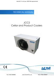
ZONE CONTROL - HEATING MODE (All outdoor units<br />
on heating)<br />
ZONE CONTROL - COOLING ONLY<br />
TO FURTHER ZONES<br />
Stage 1 Zone temperature is >0.2˚C below set-point . Valve 1 would be<br />
open, utilising the 30% coil segment.<br />
Stage 2 Zone temperature is >0.6˚C below set-point . Valve 1 would be<br />
closed and Valve 2 open, utilising the 70% coil segment.<br />
Stage 3 Zone temperature is >1.0˚C below set-point. Both valves 1 and 2<br />
would be open, utilising the full coil.<br />
Stage 4 Zone temperature >1.4˚C below set-point. Both valves 1 and 2<br />
would be open and fan speed would switch to high.<br />
Zone 1 Zone temperature is >0.2˚C above set-point. Valve 1 is open,<br />
utilising the 30% coil segment.<br />
Zone 2 Zone temperature is >0.6˚C above set-point. Valve 1 is closed but<br />
Valve 2 is open, utilising the 70% coil segment .<br />
Zone 3 Zone temperature is >1.0˚C above set-point. Both valves 1 and 2<br />
are open, utilising the full coil.<br />
Boost Cooling. Should the zone temperature exceed 1.4˚C above set<br />
point, both valves will be open and fan will automatically switch<br />
to high speed.<br />
ZONE CONTROL - COOLING MODE (All outdoor units<br />
on cooling)<br />
In cooling mode, the system operation is identical to that for heating but<br />
activated for zone temperatures above set point. All outdoor units will be<br />
operating on cooling.
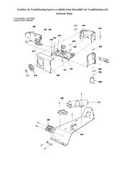
Indoor Units<br />
Three types of Indoor Unit are available: Ceiling Cassettes,<br />
Wall-Mounted and Concealed Ducted Fan Coils.<br />
Cassettes<br />
Standard Features<br />
• 2, 3 or 4 way air discharge<br />
• Condensate pump (5m lift) with overflow protection<br />
• Automatic air deflection<br />
• Mini outstation pre-loaded with relevant <strong>AQUA</strong><br />
strategy<br />
• High condensate level alarm<br />
• 70/30 split coil<br />
• Long life washable filter<br />
• Fresh air inlet facility<br />
Optional Accessories<br />
• Slave cassettes for zones requiring multiple units<br />
• Branch duct spigots for ducting conditioned air to<br />
another area<br />
• Fresh air spigots<br />
Wall-Mounted<br />
Standard Features<br />
• Tangential 2 speed fan<br />
• Mini outstation pre-loaded with relevant <strong>AQUA</strong><br />
strategy<br />
• Top or front discharge<br />
• Adjustable air louvres<br />
• 70/30 split coil<br />
• Long life washable filter<br />
Optional Accessories<br />
• Slave Fan-Coils for zones requiring multiple units<br />
• Condensate pumps (5m lift) with overflow protection<br />
Concealed Ducted<br />
Standard Features<br />
• Integral discharge plenum<br />
• Cleanable filters<br />
• Mini outstation pre-loaded with relevant <strong>AQUA</strong><br />
strategy<br />
• Centrifugal fans with 2 speed selections<br />
• Left or right hand coil connections (except AQD 70)<br />
• 70/30 split coil<br />
Optional Accessories<br />
• Slave units for zones requiring multiple units<br />
• Condensate pump (5m lift) with overflow protection<br />
• Fresh air connection<br />
• Return air plenum<br />
• A choice of spigots for either 200mm or 250mm ducting
<strong>AQUA</strong> 4 and <strong>AQUA</strong> 2 reverse cycle heat pumps*<br />
AQO models; 12, 16, 20, 25, 30, 35, 45, 90<br />
Nominal cooling capacities from 11- 81kW<br />
Heating duties from 9.5 - 74kW<br />
Standard Features<br />
• Wrap around coils<br />
• Top discharge<br />
• Plate heat exchangers • Scroll compressors<br />
• Multi blade axial fans • Auto hot gas defrost<br />
• Factory fitted isolator<br />
• Pressure operated fan speed control<br />
• Mini outstation pre-loaded with relevant <strong>AQUA</strong> strategy<br />
<strong>AQUA</strong> 2+ and <strong>AQUA</strong> MULTI air cooled chillers*<br />
AQL models; 50, 70<br />
Nominal cooling capacities 49.7 and 73.5kW<br />
Standard Features<br />
• Aluminium casing<br />
• Scroll compressors<br />
• Axial fans with head pressure control<br />
• Trend outstation pre-loaded with strategy<br />
AQL models; 100, 130, 160<br />
Nominal cooling capacities from 103.3 - 152.9kW<br />
Standard Features<br />
• Casing from galvanised steel, powder coated and stoved<br />
• Scroll compressors<br />
• Axial fans with head pressure control<br />
• Trend outstation pre-loaded with strategy<br />
AQL models; 175, 200, 250, 300, 360, 400, 500<br />
Nominal cooling capacities from 179 - 477kW<br />
Standard Features<br />
• Casing from galvanised steel, powder coated and stoved<br />
• Semihermetic compressors<br />
• Axial fans with head pressure control<br />
• Trend outstation pre-loaded with strategy<br />
Options<br />
•Full hydraulic package •Low noise versions •R407C<br />
For full design specifications please contact the Sales Applications Department.<br />
<strong>AQUA</strong> <strong>SYSTEMS</strong> CONTROL FEATURES<br />
The control system which comes as standard comprises; a central controller with an on-board modem and mini outstations<br />
within the indoor and outdoor equipment (monitoring supervision via the modem link is optional). Close temperature<br />
control is provided by four stages of output from every indoor unit, assuring optimum control and minimising temperature<br />
over-shoot from set-point.<br />
• Pre-loaded strategy<br />
• Seven day and holiday programmable timer with night-time setback and three daily time zones<br />
• Automatic staging of outdoor capacity to match indoor load<br />
• Optimised start and frost protection<br />
• Local adjustment of zone set-point temperature (optional)
,<br />
PERFORMANCE DATA INDOOR UNITS<br />
CASSETTES<br />
AQC 620 AQC 640 AQC 40 AQC 50 AQC 60 AQC 80<br />
Mode Fan PRIMARY COIL<br />
Total Low 1.36 2.47 2.36 2.60 3.70 5.06<br />
Cooling High 1.47 2.61 2.57 2.84 3.96 5.54<br />
Sensible Low 1.36 2.04 1.94 2.14 3.15 3.94<br />
Cooling High 1.47 2.28 2.29 2.53 3.64 4.58<br />
Heating Low 1.38 2.03 2.26 2.51 3.69 4.63<br />
High 1.51 2.25 2.66 2.97 4.26 5.45<br />
Flow Rate l/s 0.06 0.10 0.10 0.08 0.15 0.18<br />
SECONDARY COIL<br />
Total Low 0.67 1.43 1.16 1.62 2.11 2.22<br />
Cooling High 0.73 1.53 1.28 1.87 2.35 2.44<br />
Sensible Low 0.67 1.43 0.89 1.15 1.58 1.71<br />
Cooling High 0.73 1.53 1.05 1.37 1.84 1.99<br />
Heating Low 0.81 1.52 1.05 1.26 1.83 1.99<br />
High 0.88 1.66 1.24 1.55 2.18 2.35<br />
Flow Rate l/s 0.11 0.045 0.05 0.11 0.12 0.10<br />
BOTH COILS (ie TOTAL CAPACITY)<br />
Total Low 2.03 3.90 3.52 4.22 5.81 7.28<br />
Cooling High 2.20 4.14 3.85 4.71 6.31 7.98<br />
Sensible Low 2.03 3.47 2.83 3.29 4.73 5.65<br />
Cooling High 2.20 3.81 3.34 3.90 5.48 6.57<br />
Heating Low 2.18 3.55 3.31 3.77 5.52 6.62<br />
High 2.40 3.91 3.90 4.52 6.44 7.80<br />
SOUND PRESSURE LEVELS @3.2m distance in anechoic conditions<br />
NC Low 31 31 23 22 27 28<br />
High 34 33 30 29 35 35<br />
dBA Low 37 38 30 30 34 35<br />
High 40 39 37 36 41 41<br />
CONCEALED DUCTED<br />
AQD 35 AQD 50 AQD 70 AQD 110 AQD 200<br />
Mode Fan PRIMARY COIL<br />
Total Low 1.96 2.98 4.11 6.93 13.83<br />
Cooling High 2.10 3.30 4.65 7.65 14.42<br />
Sensible Low 1.57 2.21 3.08 5.20 10.49<br />
Cooling High 1.79 2.56 3.70 6.05 11.16<br />
Heating Low 1.87 2.55 3.42 6.10 12.33<br />
High 2.14 3.01 4.18 7.26 13.24<br />
Flow Rate l/s 0.09 0.15 0.19 0.27 0.66<br />
SECONDARY COIL<br />
Total Low 1.27 1.65 2.11 3.40 6.92<br />
Cooling High 1.42 1.87 2.40 3.99 7.17<br />
Sensible Low 0.92 1.18 1.56 2.33 5.25<br />
Cooling High 1.06 1.38 1.88 2.80 5.54<br />
Heating Low 1.04 1.32 1.78 2.37 6.17<br />
High 1.22 1.59 2.22 2.87 6.56<br />
Flow Rate l/s 0.14 0.12 0.10 0.16 0.33<br />
BOTH COILS (ie TOTAL CAPACITY)<br />
Total Low 3.23 4.63 6.22 10.33 20.75<br />
Cooling High 3.52 5.17 7.05 11.64 21.57<br />
Sensible Low 2.49 3.39 4.64 7.53 15.74<br />
Cooling High 2.85 3.94 5.58 8.85 16.70<br />
Heating Low 2.91 3.86 5.20 8.74 18.50<br />
High 3.36 4.60 6.40 10.13 19.80<br />
SOUND PRESSURE LEVELS*<br />
NC 32 33 37 33 T.B.A.<br />
dBA 42 44 44 46 T.B.A.<br />
*Measurements taken @3.2m distance in a typical hotel bedroom at low fan speed.<br />
All indoor unit capacities are in kW and for a 20% by weight glycol solution at designated flow rate.<br />
Cooling conditions <strong>Air</strong> on23˚C dry bulb, 50% rh<br />
Glycol on<br />
4˚C<br />
Power requirements 220-240V, 1 Ph, 50 Hz (5A)<br />
Heating conditions <strong>Air</strong> on<br />
Glycol on<br />
21˚C<br />
40˚C<br />
WALL-MOUNTED<br />
AQW 20 AQW 40 AQW 60<br />
Mode Fan PRIMARY COIL<br />
Total Low 0.93 1.99 3.41<br />
Cooling High 1.10 2.16 3.70<br />
Sensible Low 0.66 1.59 2.67<br />
Cooling High 0.81 1.85 3.05<br />
Heating Low 0.73 1.88 3.14<br />
High 0.92 2.17 3.62<br />
Flow Rate l/s 0.13 1.10 0.15<br />
SECONDARY COIL<br />
Total Low 0.45 1.21 1.79<br />
Cooling High 0.55 1.37 1.99<br />
Sensible Low 0.30 0.85 1.30<br />
Cooling High 0.39 0.99 1.49<br />
Heating Low 0.32 0.95 1.47<br />
High 0.43 1.12 1.72<br />
Flow Rate l/s 0.19 0.15 0.13<br />
BOTH COILS<br />
(ieTOTAL CAPACITY)<br />
Total Low 1.38 3.20 5.20<br />
Cooling High 1.65 3.53 5.69<br />
Sensible Low 0.96 2.44 3.97<br />
Cooling High 1.20 2.84 4.54<br />
Heating Low 1.05 2.81 4.61<br />
High 1.35 3.29 5.34<br />
SOUND PRESSURE LEVELS**<br />
NC Low 25 26 21<br />
High 28 31 28<br />
dBA Low 30 32 27<br />
High 34 36 34<br />
**@3m distance in anechoic conditions.<br />
For dimensions contact Sales Applications Department.<br />
<strong>AQUA</strong> 2+ cooling coil duties as <strong>AQUA</strong> 4 (2)<br />
primary coil figures.<br />
<strong>AQUA</strong> 2+ Heating coil duties (kW);<br />
Low<br />
High<br />
Cassettes 2.55 10.22<br />
Ducted 5.26 34.76<br />
Wall 2.14 8.2<br />
Conditions; Heating flow / return temperatures 80 0 C / 65 0 C<br />
Heating coil flow rate l/s as secondary coil<br />
<strong>AQUA</strong> 4 (2)<br />
<strong>AQUA</strong> MULTI cooling coil duties as <strong>AQUA</strong> 4 (2)<br />
for primary coil, secondary coil and<br />
both coils (i.e. total capacity).<br />
All indoor unit capacities are in kW and for a 20% by weight glycol solution at<br />
designated flow rate.<br />
Cooling conditions <strong>Air</strong> on23˚C dry bulb, 50% rh<br />
Glycol on<br />
4˚C<br />
Power requirements 220-240V, 1 Ph, 50 Hz (5A)<br />
IMI <strong>Air</strong> <strong>Conditioning</strong> <strong>Ltd</strong><br />
IMI <strong>Air</strong> <strong>Conditioning</strong> <strong>Ltd</strong><br />
Armytage Road, Brighouse<br />
W est Yorkshire H D 6 1 QF,England<br />
Tel: +44 (0)1484 405600<br />
Fax: +44 (0)1484 721949<br />
w w w.imi-airconditioning.co.uk<br />
A subsidiary company of IMI plc<br />
T B A<br />
Products comply fully with stringent<br />
HM British Government Specification<br />
SEG 136/1.<br />
IMI <strong>Air</strong> <strong>Conditioning</strong> products are<br />
designed and manufactured in the UK<br />
and are suitable for a range of ambient<br />
conditions. For full design information,<br />
reference should be made to the<br />
relevant technical manual. Our policy<br />
is one of continuous improvement and<br />
we reserve the right to alter designs<br />
and specifications at any time without<br />
notification.<br />
06617543-CD<br />
Approved to<br />
B S EN ISO 9001<br />
Certificate No. FM 671