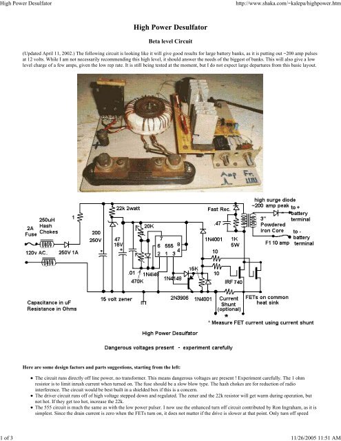
High Power Desulfator.pdf - AeroElectric Connection
High Power Desulfator.pdf - AeroElectric Connection
High Power Desulfator.pdf - AeroElectric Connection

You also want an ePaper? Increase the reach of your titles
YUMPU automatically turns print PDFs into web optimized ePapers that Google loves.
<strong>High</strong> <strong>Power</strong> <strong>Desulfator</strong><br />
http://www.shaka.com/~kalepa/highpower.htm<br />
1 of 3 11/26/2005 11:51 AM<br />
<strong>High</strong> <strong>Power</strong> <strong>Desulfator</strong><br />
Beta level Circuit<br />
(Updated April 11, 2002.) The following circuit is looking like it will give good results for large battery banks, as it is putting out ~200 amp pulses<br />
at 12 volts. While I am not necessarily recommending this high level, it should answer the needs of the biggest of banks. This will also give a low<br />
level charge of a few amps, given the low rep rate. It is still being tested at the moment, but I do not expect large departures from this basic layout.<br />
Here are some design factors and parts suggestions, starting from the left:<br />
The circuit runs directly off line power, no transformer. This means dangerous voltages are present ! Experiment carefully. The 1 ohm<br />
resistor is to limit inrush current when turned on. The fuse should be a slow blow type. The hash chokes are for reduction of radio<br />
interference. The circuit would be best built in a shielded box if this is a concern.<br />
The driver circuit runs off of high voltage stepped down and regulated. The zener and the 22k resistor will get warm during operation, but<br />
not hot. If they get too hot, increase the 22k.<br />
The 555 circuit is much the same as with the low power pulser. I now use the enhanced turn off circuit contributed by Ron Ingraham, as it is<br />
simplest. Since the drain current is zero when the FETs turn on, it does not matter if the drive is slower at that point. Only turn off speed
<strong>High</strong> <strong>Power</strong> <strong>Desulfator</strong><br />
http://www.shaka.com/~kalepa/highpower.htm<br />
2 of 3 11/26/2005 11:51 AM<br />
matters for maximum effect. The pulse width is anywhere from 10 to 100uSecs, depending on what is desired for peak output current.<br />
The output FETs are paralleled together on a common heat sink. They get only slightly warm during operation, so it does not need to be<br />
large. At the moment I am using 3 IRF740's, this is probably on the safe side as they do not get warm. Other FETs can be used if they have<br />
low on resistance and a 400 volt rating.<br />
The snubber circuit uses a fast 200V diode, a 1k 5W resistor, and a .47 250V capacitor. This is a traditional approach to limiting peak<br />
transients, and works well enough. The dissapation here can be reduced as the transformer is further optimised.<br />
The transformer is wound on a core from Bytemark. It is powdered iron, 3 inches in diameter, part number T-300A-26. One could probably<br />
use the next size down as well. The primary is at the moment 60 turns of no. 18 to 20 enameled wire. Cover the primary with a layer of<br />
insulation, preferably of transformer tape (or at least not black electrician's tape.) There are four secondary windings of ten turns each, no.12<br />
or14 wire. They are wound in "quadra-filar" fashion, which means they are placed side by side and wrapped around together in the form of<br />
a ribbon. The windings should all be evenly spaced and spread uniformly around the circumference of the core. This is done to reduce stray<br />
inductance. Note the polarity of the windings. All the windings are done in the same direction. The primary lead which connects to the high<br />
voltage line will be a beginning point. The secondary winding which connects to the diode will therefore also be a beginning point. If the<br />
polarity of the secondary is reversed, then you will not get a proper current spike. Here is a diagram to show this:<br />
For 12 volt batteries, use all the secondaries in parallel, ie. S1, S2, S3, S4 are all tied together, and E1, E2, E3, E4 are all tied together. For<br />
24 volt batteries, use series connections to increase the voltage, just like a normal transformer. This means use the windings in pairs, and<br />
connect the ending of one paired winding to the beginning of the other, ie S1-S2 is connected together, E1-E2 and S3-S4 are all connected<br />
together (the center tap, which is not otherwise used), and E3-E4 are connected together. For 48 volts systems, use the four windings in<br />
series, or S2 to E1, S3 to E2, S4 to E3, S1 and E4 are the output leads. Note that the peak current will be reduced at the higher voltages. For<br />
120 volt EV batteries, a more straightforward 1:1 transformer should work, with primary and secondary each made with #12 wire. The<br />
windings would be made in bifilar fashion.<br />
The output rectifier is a high current, reasonably fast type. At the lowest voltage, a Schottky diode, such as the 60 amp 45 volt<br />
STPS6045CW from ST Microelectronics gives good efficiency. (Mouser catalog part no. 511-STPS6045CW) . Mount it on a small heat<br />
sink. At higher voltages, try a 20 amp 100 volt STPS20H100CW, which has lower current but higher voltage rating. They can be paralleled<br />
for higher current. At the highest voltages, 400 volt, 35 amp fast recovery units are needed. It is important to have a load connected before<br />
applying power, otherwise the FETs could receive a damaging spike.<br />
The theory behind this type of circuit can be seen on this page of DC to DC converter designs.<br />
Adjust the circuit with the variable resistors on the 555: The 470K resistor adjusts rep rate, and should be set to less than 1kHz. The 20k resistor is<br />
pulse width, and should be set such that the transformer core is not starting to saturate- in the neighborhood of 100 usecs. The circuit as a whole<br />
should draw around .2A @ 120VAC or less. In my tests on the bench I can get over to 200 A peak current out at low voltage. Less peak current<br />
will be possible at the higher voltages. However, one only needs to duplicate the transformer, and add more FETs in parallel to get further<br />
increases in peak power.<br />
Be careful in probing the circuit with a scope. I have been advised that a half wave rectifier, at the line input, should be used so that people won't<br />
get confused by creating ground loops with scope probes, etc. It seems that the full wave bridge is not really needed as ripple is not much of a<br />
concern with this circuit. Make sure that you observe correct polarity at the mains connection point, so that ground is indeed grounded.<br />
For those who wish to drive this circuit from a microcontroller chip, use an optocoupler for protection. The following diagram will enable a simple<br />
logic level interface, using the Isocom H11L2 (from Digikey.) This unit has a strong pull down output, and is reasonably fast. Other types will be<br />
fine, as long as they have a low turn current input(10mA or less) and a fast darlington or schmidt trigger output.
![G-Series-Ext [pdf] - Carling Technologies](https://img.yumpu.com/50918301/1/190x245/g-series-ext-pdf-carling-technologies.jpg?quality=85)