tutorial for using the laser plotter
index
- checking that the cutting file is suitable for the dimensions of the laser plotter
- managing the layers
- defining the cutting order of the layers
- setting the parameters for cutting and/or engraving
- creating a new layer
- checking cutting times
- turning on the plotter
- inserting the material into the machine
- focusing
- turning on the fumes aspiration system
- starting the cut
- at the end of the cut
- advanced procedures – staff operators only
- advanced settings – staff operators only
- a. how to determine the parameters for cutting, engraving and scanning
- b. RDWorks in Chinese
- c. PC does not communicate with the plotter
- d. IP address of the plotter
- e. installing the RDWorks software
- f. error in the cutting order of the layers
- g. cutting order dall’interno all’esterno (from inside to outside)
- h. shortening engraving times for fillers and raster images
- i. reading machine work time
- checklist for operators
- prohibitions and regulations
- machine sheets
- instructions manuals
- tutorial for using the laser plotter – printable version
1. checking that the cutting file is suitable for the dimensions of the laser plotter

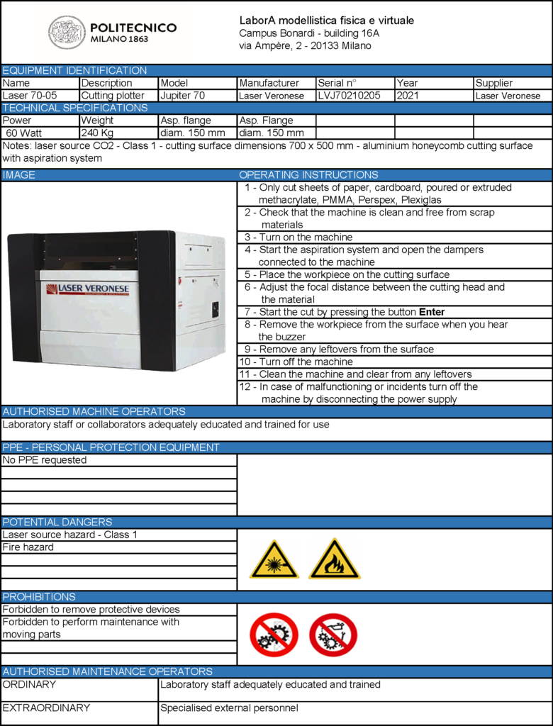
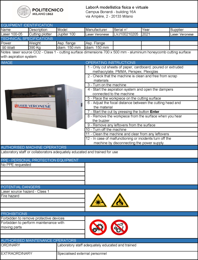
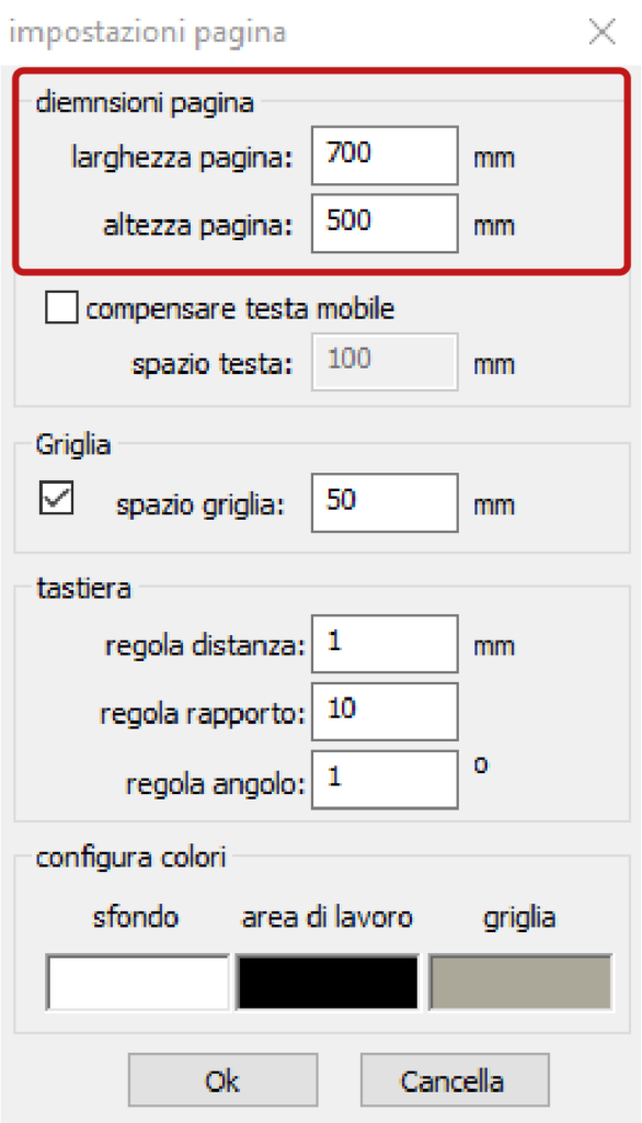
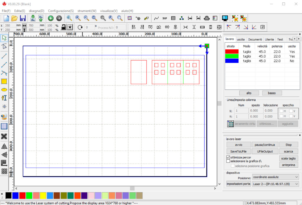
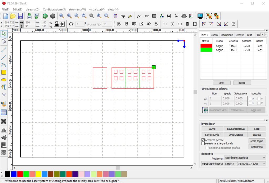
When the software opens, it is presented with a frame containing a square grid which corresponds to the representation of the machine working area. This working area must have a dimension of 700 x 500 mm in lasers 1 and 2 and of 1000 x 700 mm in laser 3.
Check that the working area of the software RDWorks connected to the plotter that you intend to use has the correct dimensions.
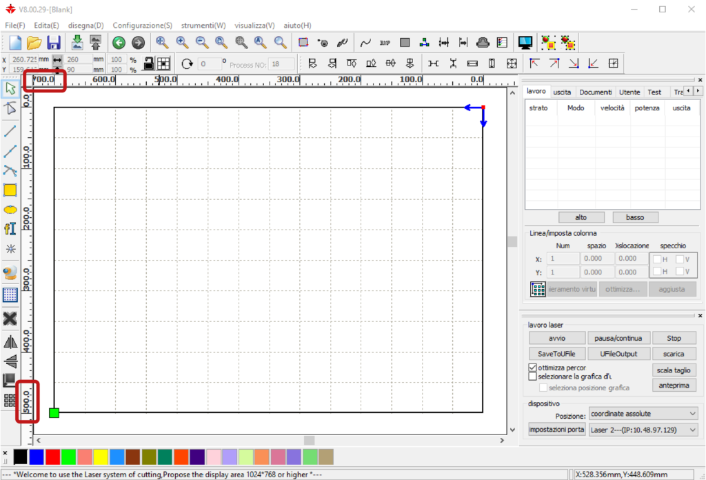
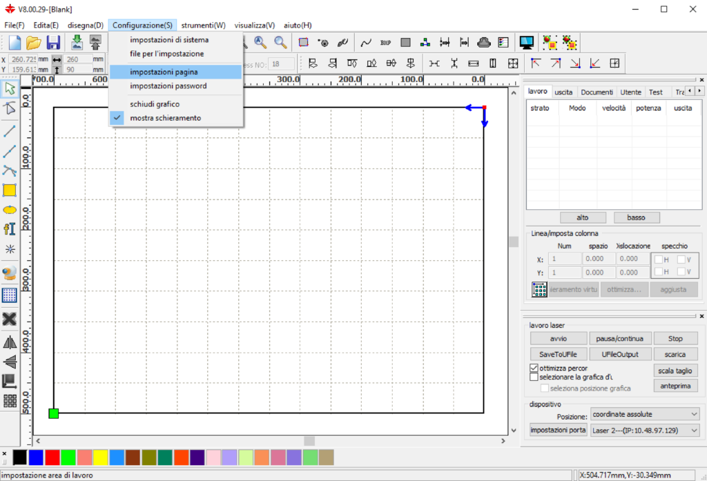
If that is not the case, it is necessary to change them from the main menu of the software Configurazione(F) > Impostazioni pagina (Configuration > Page settings)
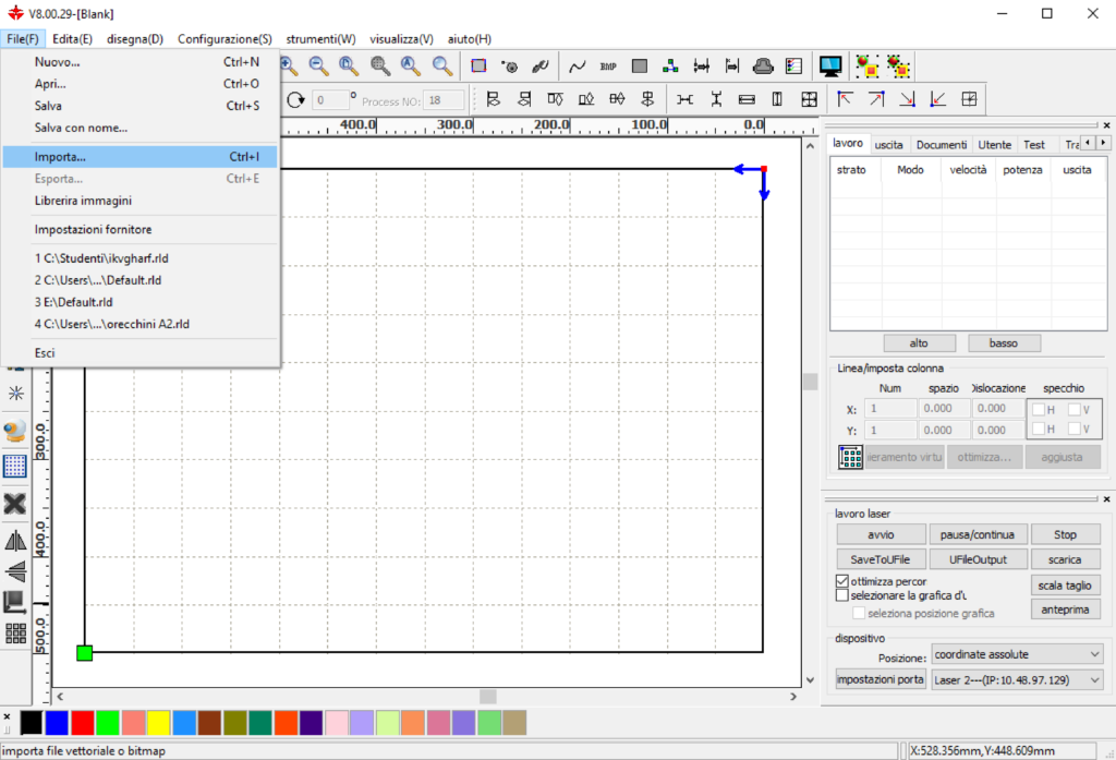
To import the file containing the geometries to be cut, which must be in .dxf 2000 format, from the main menu of the software select File(F) > Importa…
As shown in the laser cutting page, the drawings of the pieces to be cut must be placed inside two or three blue frames: the outer frame, if drawn with the correct dimensions in relation to the plotter you intend to use and if the dimensions of the working area are correct, should match the outline of the squared grid/working area. In this case, the second frame delimits the cutting area on the honeycomb plane.
If, on the other hand, the outer frame appears larger than the working area, it means that the file was set up to be cut with the laser 3.
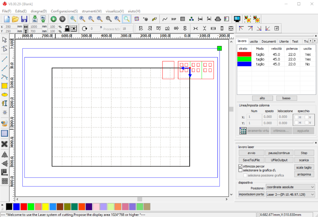
In this second case, either edit the drawing file and place the pieces inside a 700 x 500 mm frame or (if available) use laser 3 to cut the pieces.
If, once the drawing file has been imported into the RDWorks software, the outer frame appears smaller than the working area, it means that the file was imported on the computer connected to laser 3, but the drawing file was set up to be cut with lasers 1 and 2.
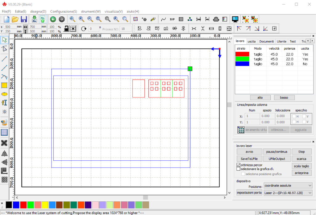
In this case too, it will be necessary to edit the file and place the pieces inside a 1000 x 700 mm frame or (if available) use lasers 1 and 2 to cut the pieces.
2. managing the layers
The RDWorks software automatically assigns different layers (called strati) to the drawing elements, based on their source colour.
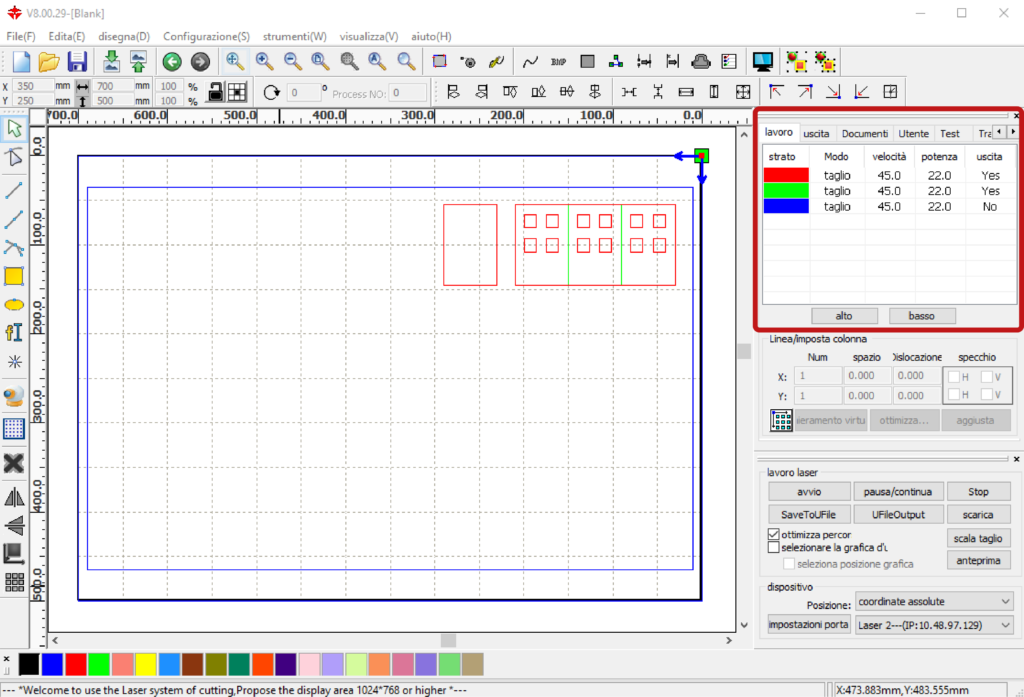
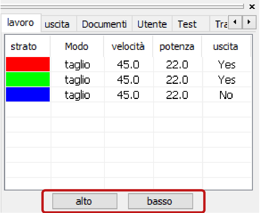
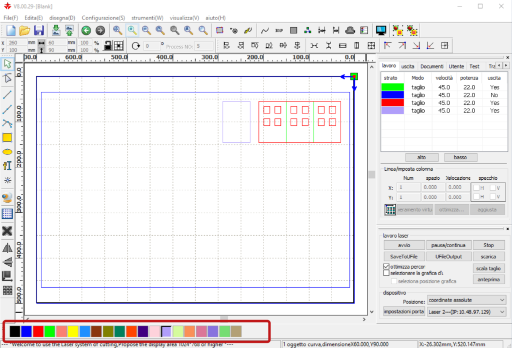
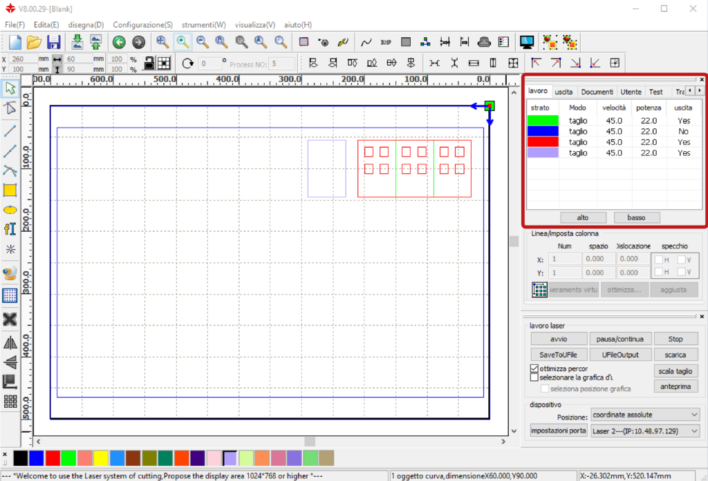
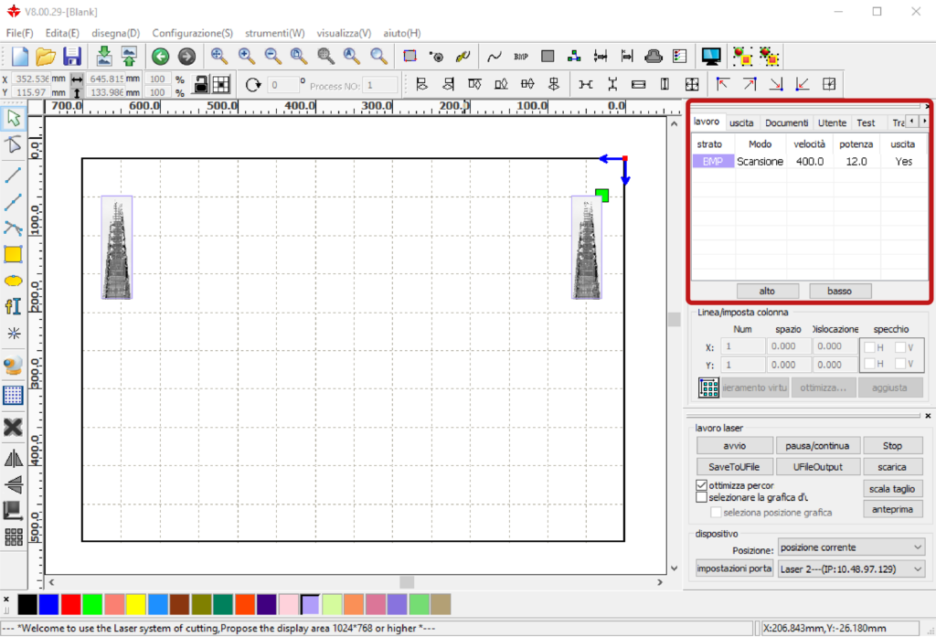
In the top right panel, in the lavoro (work) section, the layers created by the software are presented with the processing parameters: Modo (method), velocità (speed), potenza (power) e uscita (output), that were set for that colour in the last working session.
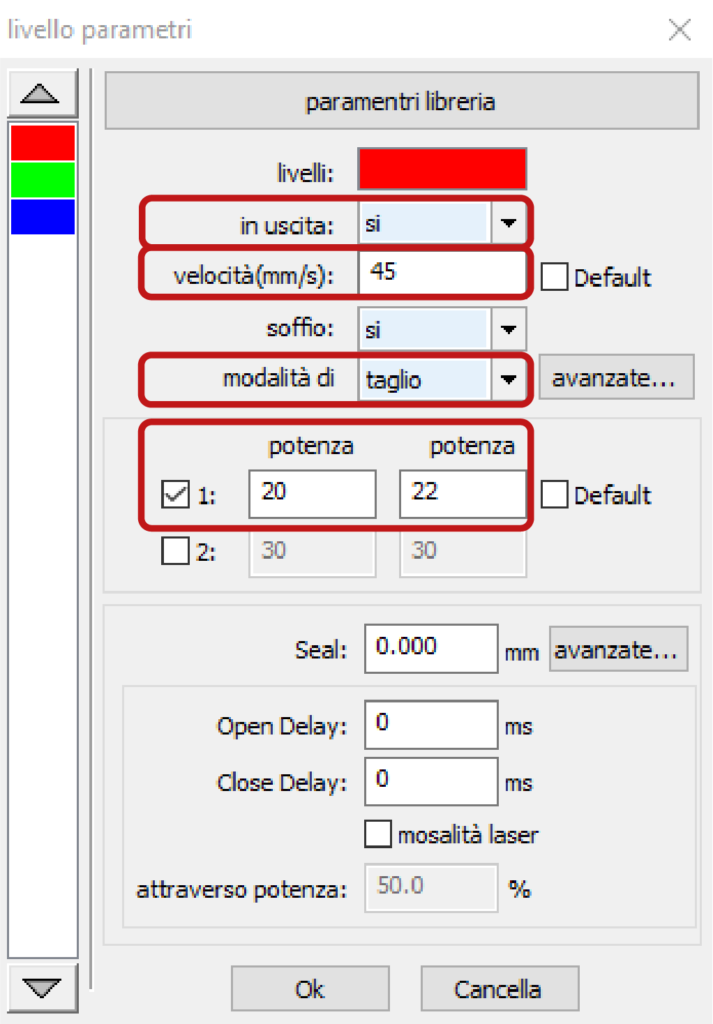
To change these values, double-click on the assigned layer. In the window livello parametri the item modalità di determines the type of processing taglio (for cutting and engraving) and scansione (for filler engravings). The item in uscita determines whether or not the processing is sent to the plotter. The items velocità and potenza determine the cutting or engraving of the material according to its type and thickness.
3. defining the cutting order of the layers
The automatic definition by RDWorks of layers also determines their processing order, starting from the first one at the top of the window lavoro.
If necessary, you can either change this order by selecting the layer and dragging it to the desired position, or by using the buttons alto and basso at the bottom of the window.
Defining the cutting order is necessary, for example, if engravings are to be made: these must be realised before the cuts, to prevent the pieces from moving during the incision.
4. setting the parameters for cutting and/or engraving
To cut or engrave different materials, or the same material in different thicknesses, it is necessary to assign appropriate speed and power parameters to each of the layers. This is so that the cut turns out as clean as possible without causing excessive burning.
In the top right panel in the section lavoro, double-click on one of the layers to open the related window livello parametri.
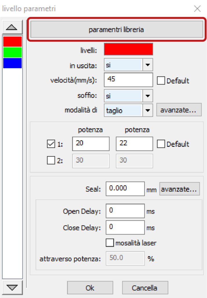
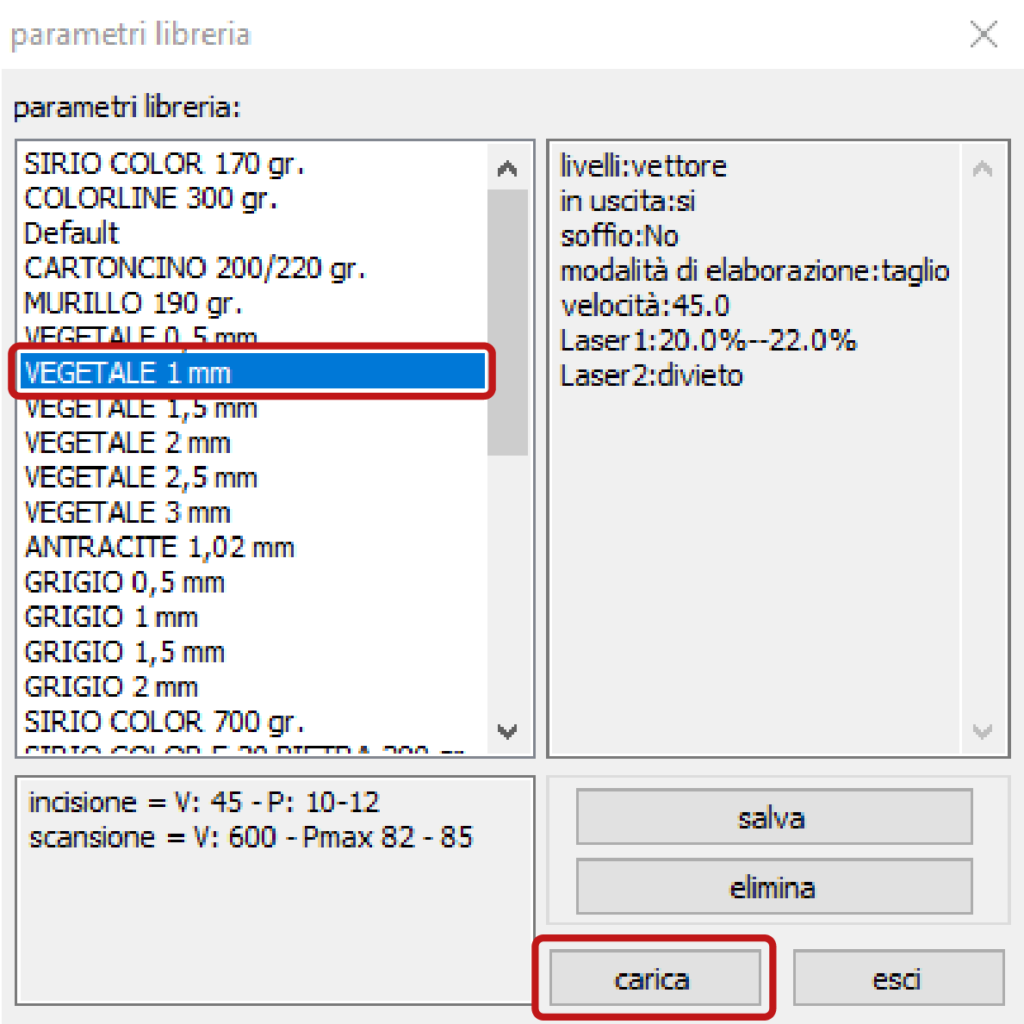
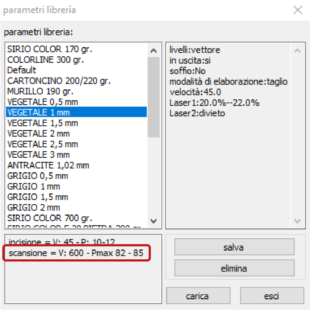
To select the material to be cut according to its type and thickness, click on the button parametri libreria and in the window parametri libreria confirm the choice with the button carica (load).
This choice only concerns the assignment to a layer of the cutting parameters of a given material of a given thickness.
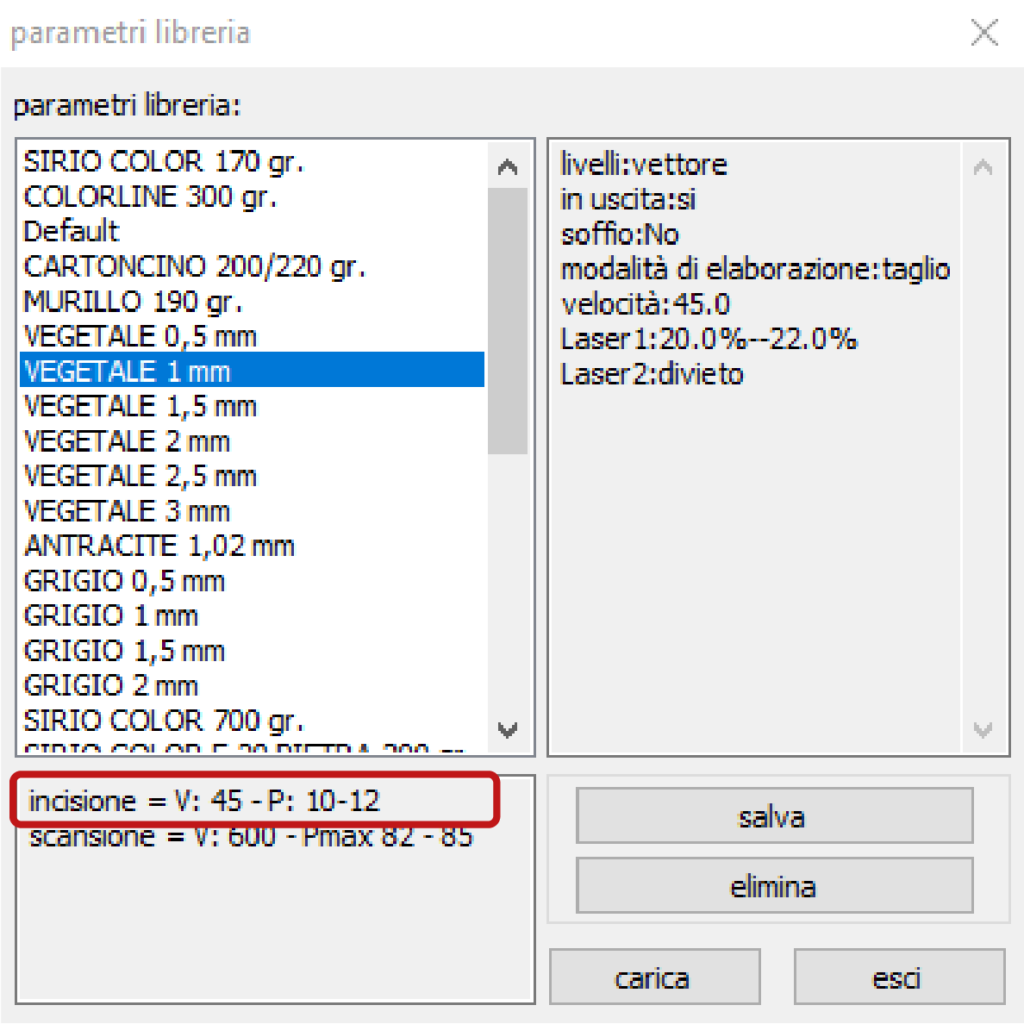
In the case of engraving, the parameters velocità and potenza, which can be found in note in the same window parametri libreria, must be assigned manually to the layer in the respective boxes.
If the parameters for engraving are not present, it is necessary to identify them following the instructions in the next chapter 13 paragraph a. OPERATORS AND STAFF ONLY and add them as a note to the material in the window parametri libreria.
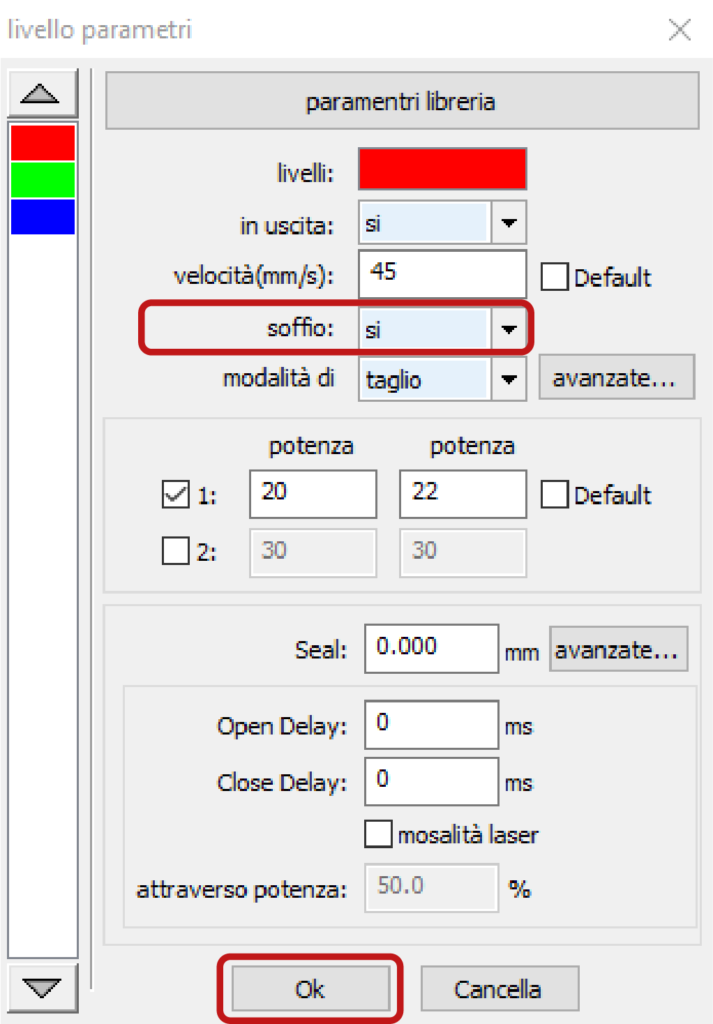
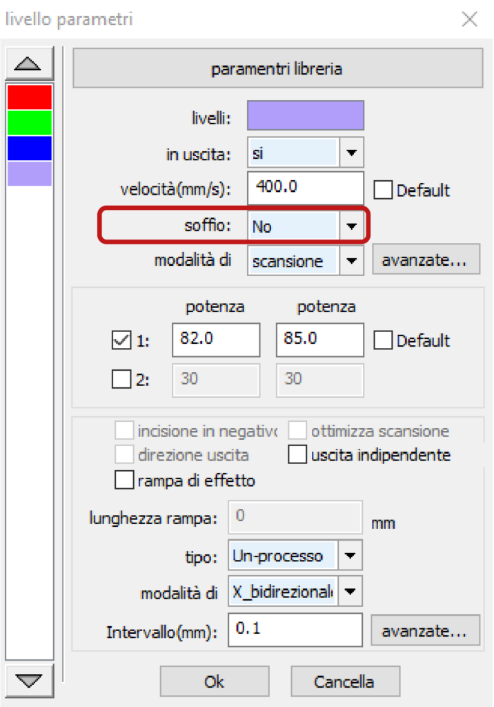
In the window parametri libreria, in addition to the parameters of speed and power, you need to check the parameter soffio (blow), which in the case of materials such as: cardboards and similar, must be set to sì. While in the case of methacrylate, it must be set No.
Confirm the choices in the window parametri libreria with the Ok button.
If, once the cutting parameters saved in the window parametri libreria have been loaded, the material is not cut, it is necessary to gradually increase the power or decrease the speed. But if the cutting parameters deviate too much from the saved ones, it may be necessary to clean the lens, to be requested TO OPERATORS AND STAFF ONLY.
5. creating a new layer
To set different cutting/engraving parameters for certain elements of the drawing, it is necessary to create a new layer containing these elements and assign the desired parameters to the layer. The creation of a new layer occurs automatically when, after selecting the elements of the drawing, you assign them a new colour by choosing it in the bar at the bottom left of RDWorks.
6. checking cutting times
To check the time taken by the plotter for cutting, based on the set parameters, preview the processing by clicking the icon from the main menu.
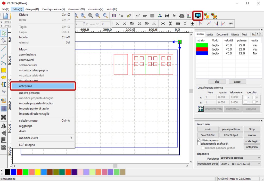
The Anteprima (preview) window will open.
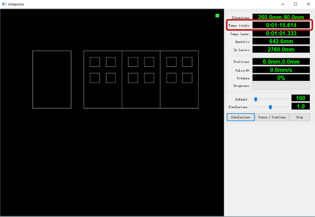
The Tempo totale (total time) to take into account for scheduling appointments is displayed in the top right panel. By starting the Simulazione (simulation) it will be possible to visualize the path of the cutting head.
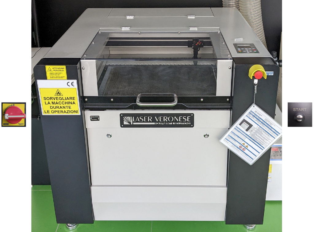
7. turning on the plotter
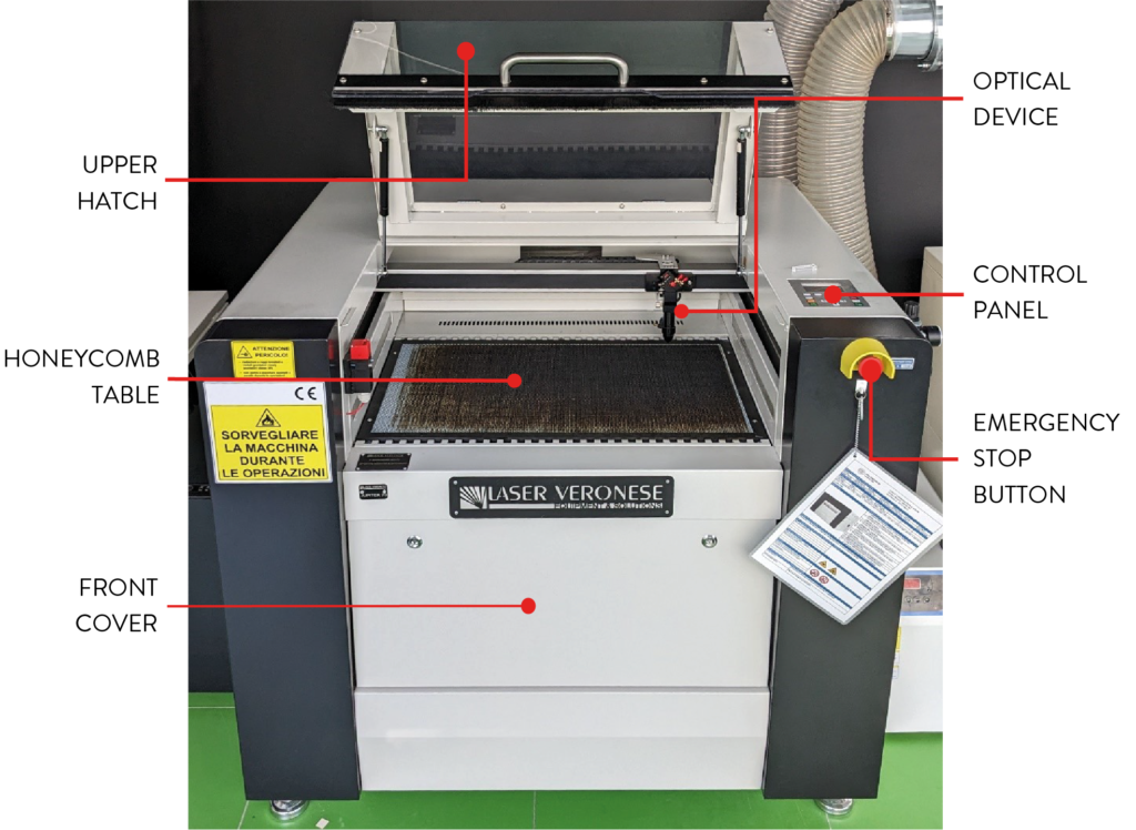
To turn on the laser plotter, first electrically power the machine by turning the red handle on the left side and then start it by turning the key on the right side.
8. inserting the material into the machine
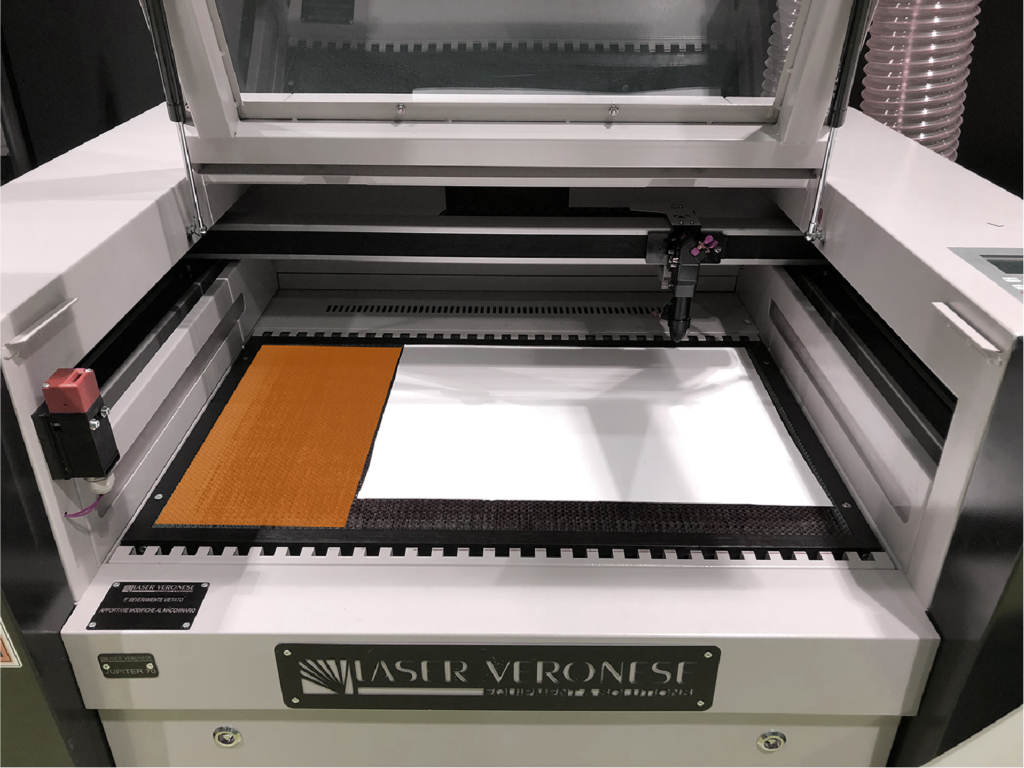
Insert the material into the machine by opening the upper door.
Materials such as: cardboard and similar, must be layed on the honeycomb panel by placing the sheet in the upper right corner inside the metal frame.
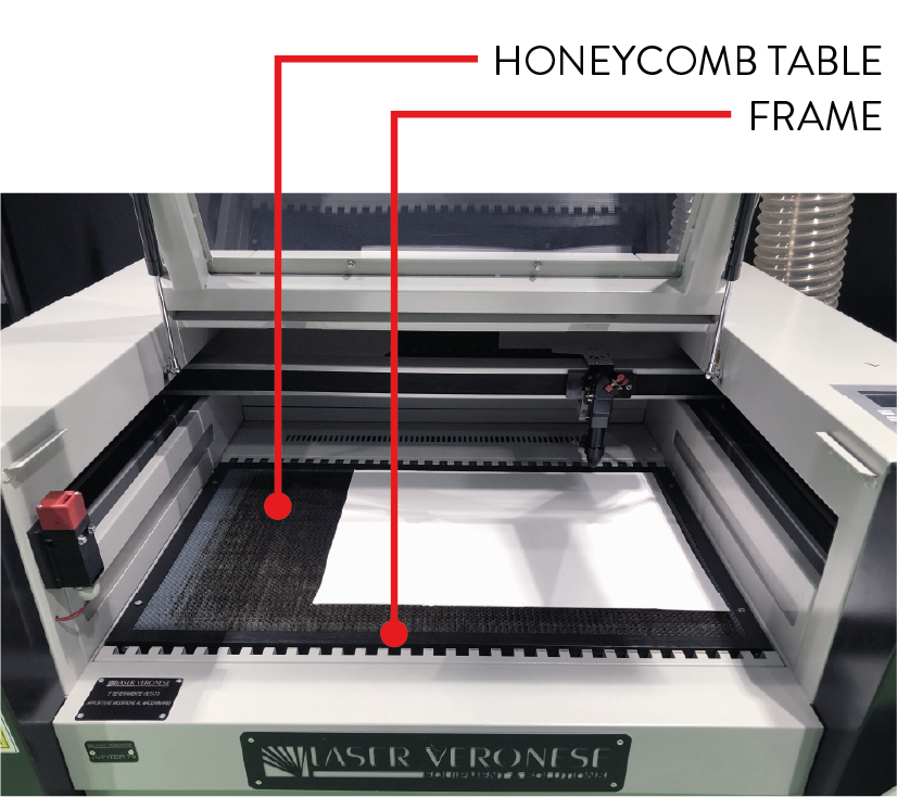
The honeycomb panel inside the metal frame has dimensions of 700 x 430 mm in lasers 1 and 2 and dimensions of 1000 x 630 mm in laser 3. The material to be cut must therefore not exceed these maximum dimensions in order to lie flat without overlapping the metal frame.
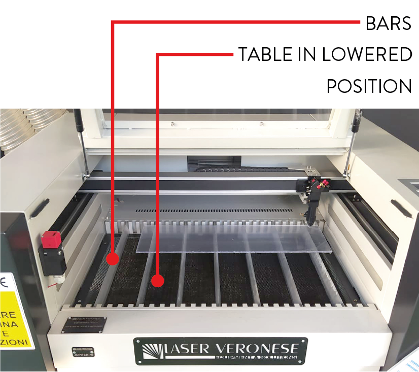
To cut rigid sheets, such as methacrylate, and achieve the best cutting cleanliness, it is necessary to place the material on bars and not on the honeycomb panel. Please contact the staff to arrange this type of support.
9. focusing
Before proceeding with cutting or engraving, the lens inside the laser head must be focused on the surface of the material.
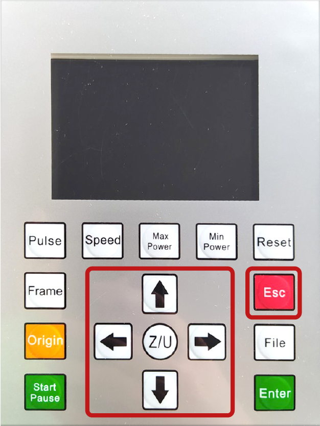
Move the laser head towards the centre of the material, to a position where it does not interfere with the metal frame, using the arrows on the control panel of the machine.
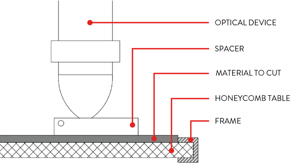
Take the spacer (A) that is found next to the control panel of the machine and place it under the tip of the laser head.
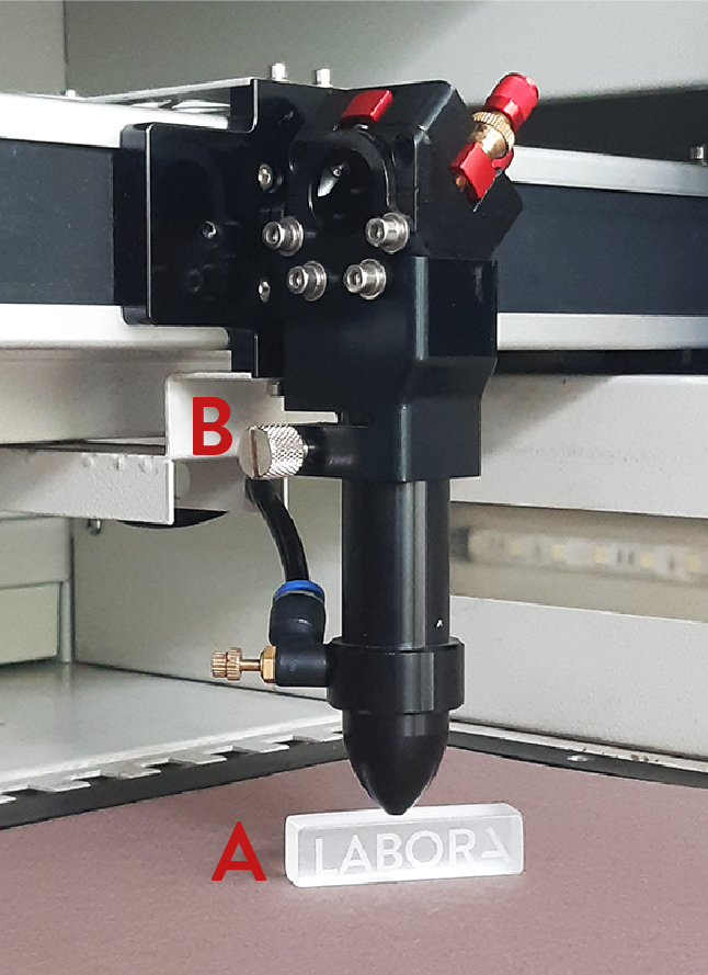
Manually loosen the screw (B) on the left side of the laser head to allow the tube containing the lens to move vertically until it leans against the spacer.
With the tube still resting on the spacer, tighten back the screw (B), remove the spacer, press the red Esc button on the control panel and wait for the laser head to return to the resting position in the upper left corner.
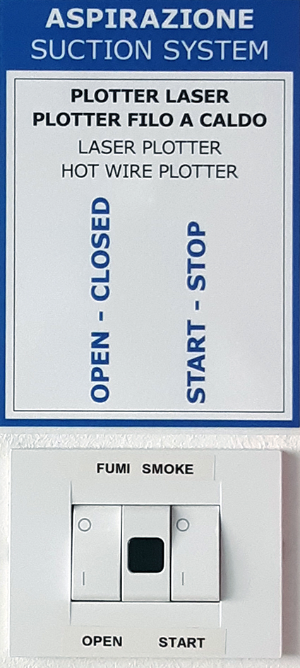
10. turning on the fumes aspiration system
Before starting the cutting operations turn on the fumes aspiration system or check that it is already turned on and open the aspiration damper connected to the plotter you intend to use.
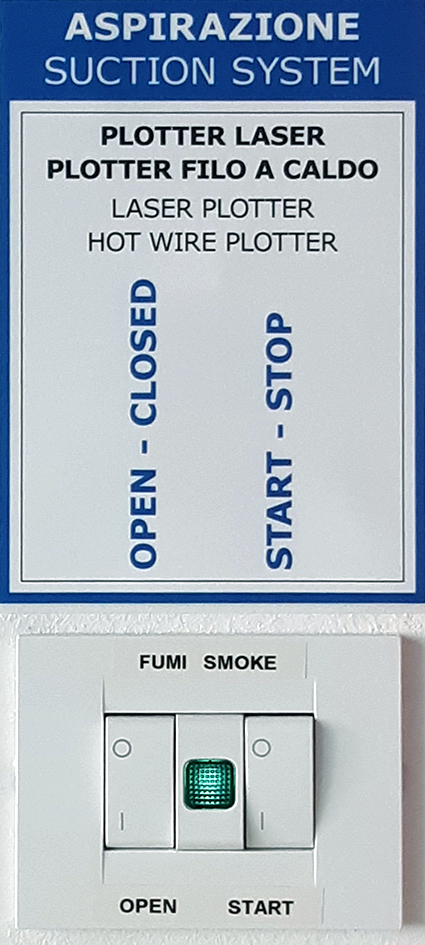
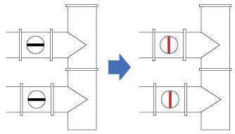
Every laser plotter is equipped with two aspiration pipes, to open the dampers turn them both, placing them in a horizontal position.
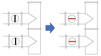
In the case of laser plotters, the air system not only eliminates cutting fumes, but also helps to keep the material still and adherent to the honeycomb panel, preventing the laser beam from going out of focus and and the cut pieces from moving. Therefore, to ensure the best possible aspiration, check that the dampers on the pipes connected to machines that are not in use are closed, including the hot wire cutter.
If the material to be cut is smaller than the honeycomb surface and the aspiration is insufficient to hold it in place, cover the remaining part of the top with other cardboard.
11. starting the cut
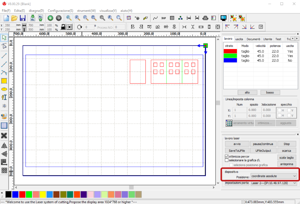
The cut is managed directly by the RDWorks software in the panel lavoro laser located at the bottom right of the main screen.
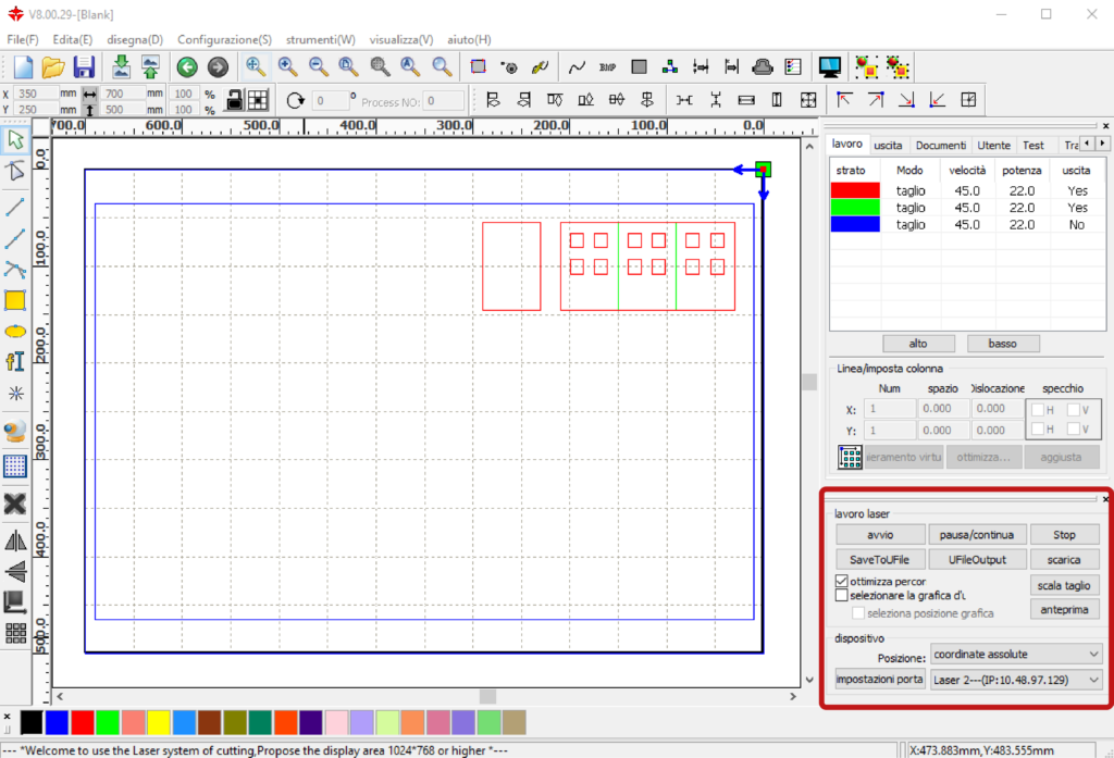
In this panel, before starting the cut, you must define the starting point by setting the item Posizione (position) in coordinate assolute (absolute coordinates) in the section dispositivo (device).
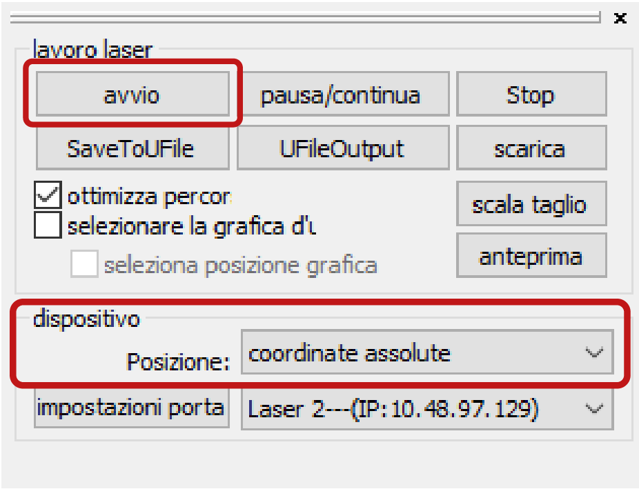
To start the cut, close the upper door of the machine and in the menu lavoro laser click avvio (start).
DURING CUTTING REMAIN NEXT TO THE MACHINE TO MONITOR ITS CORRECT OPERATION.
12. at the end of the cut
The end of the cut is signalled by the plotter with a buzzer, at which point open the upper door and retrieve the cut pieces.
CLEANING THE PANEL: remove the residues from the honeycomb panel.
TURNING OFF THE MACHINE: first turn the key and then switch off the voltage by turning the red knob: opposite procedure from turning it on, chapter 6.
CLOSING THE DAMPERS: close both dampers on the exhaust pipes connected to the plotter, returning them to a vertical position.
TURNING OFF THE AIR SYSTEM: return in position O the two switches on the right of the CNC LAB door.
LEAVE THE SYSTEM TURNED ON IF THERE ARE OTHER LASER PLOTTERS OR THE HOT WIRE PLOTTER IN OPERATION IN THE CNC ROOM: BOTH SWITCHES IN POSITION “I”
IN THE EVENT OF MALFUNCTION, PRESS THE EMERGENCY STOP BUTTON ON THE FRONT RIGHT OF THE MACHINE AND CALL THE STAFF.
13. advanced procedures – staff operators only
a. changing the starting point of the cut
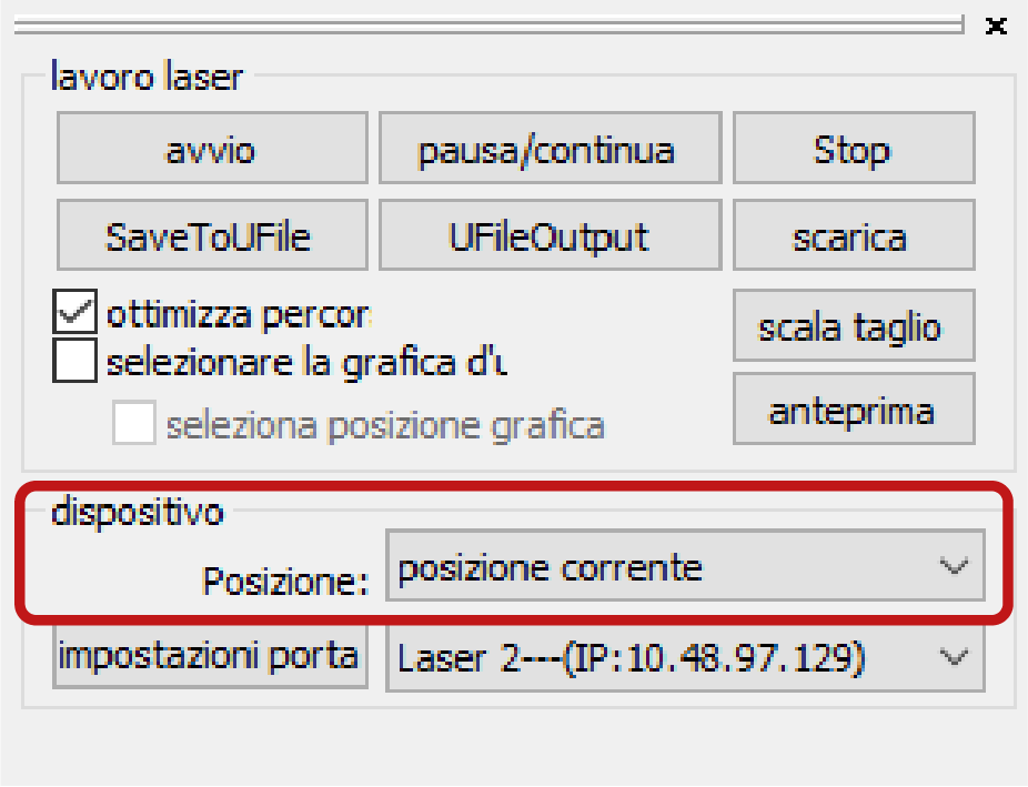
The starting point of the cut, displayed in the drawing area with a green square, is usually set in Posizione: coordinate assolute and corresponds to the upper right corner of the plotter’s working area.
For some cuts, however, it may be useful to set a starting point of the cut relatively to the drawn geometries, by setting in the panel lavoro laser, on the bottom right, the item Posizione: in posizione corrente (current position).
In order to determine the current position, the software considers all drawn elements, even if they are placed on layers that will not be cut, such as frames, which is why they must be deleted directly in RDWorks.
Before starting the cut in the software, it is necessary to set the starting point in the plotter.
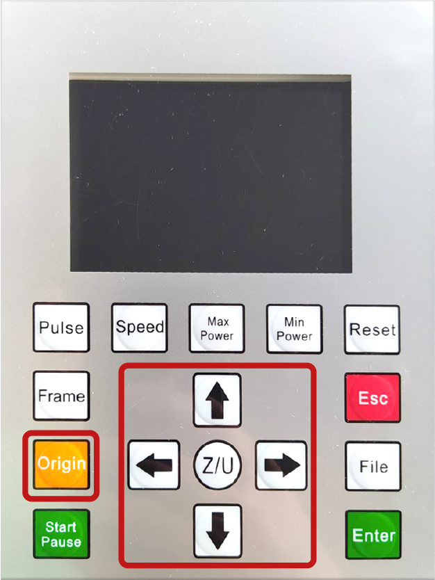
On the control panel of the machine, move the laser head with the arrows until you reach the desired point for the start of the cut, then press the Origin button to record it as posizione corrente (current position). This relative origin remains valid for all the following cuts that are set in posizione corrente, until the input of a new Origin or until the plotter is turned off.
b. using the maximum working area
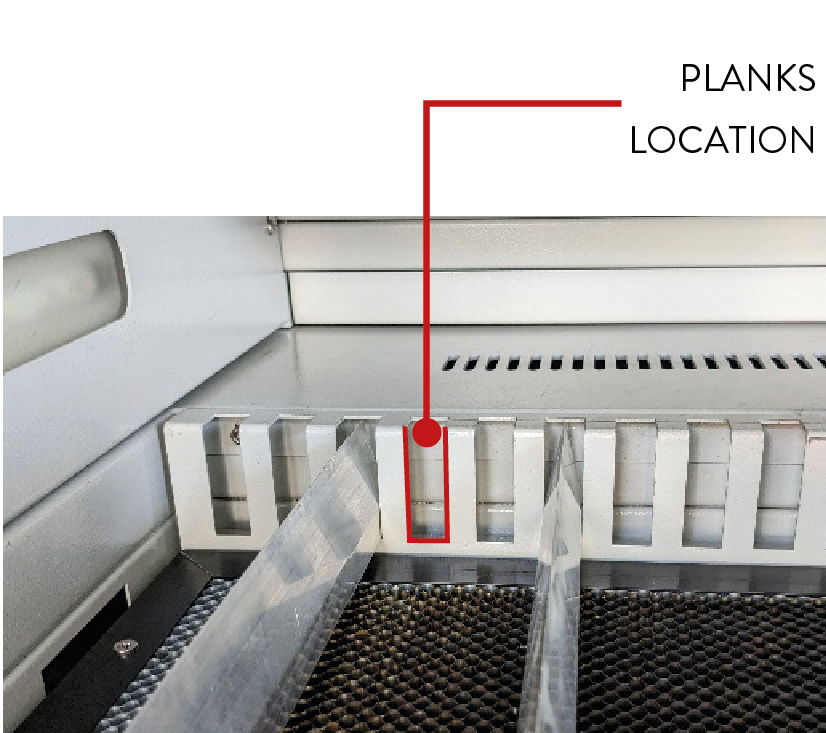
To fully exploit the working area of the plotter, which is larger than the normal cutting area on the honeycomb panel, it is possible to place the material on support planks.
Using the planks is recommended for cutting rigid panels such as plywood or mdf and transparent methacrylates: the planks limit the support surface of the material, reducing the burn marks on the underside of the material.
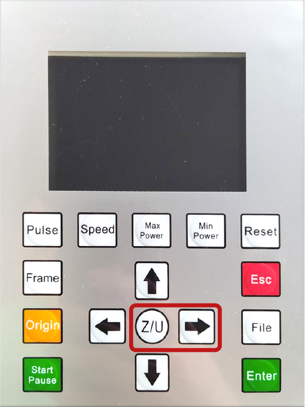
To place the planks, it is necessary to lower the honeycomb panel below the seat of the planks. On the control panel of the plotter press the Z/U button, then lower the panel by pressing and holding down the right arrow.
TURN OFF THE PLOTTER, by turning the key on the right side only, before taking the planks which are located inside the machine. Open the front door with the specific key that is found in the drawer CS1 of the CNC lab, pull out the planks, then close the panel and restart the plotter.
Place as few planks as possible, as long as the sheet does not bend due to its weight or the aspiration.
c. engraving of fillers
The realize a filler, which means to engrave by burning the entire inner surface of a closed figure, use the mode scansione (scan). In the top right menu in the section lavoro, double-click on the layer that contains the figures to be filled in order to open the related window livello parametri.
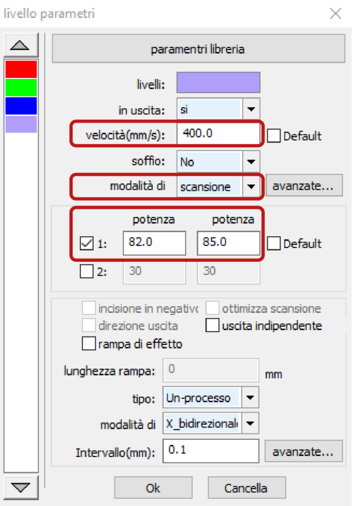
Set the item modalità di on scansione. For the items velocità (speed) and potenza (power), copy the values related to scansione found in the note for each material in the window parametri libreria.
In the window livello parametri, in addition to speed and power parameters, it is necessary to check the parameter soffio (blow), which is advisable to set to No in the case of procedures in modalità di scansione to keep the surface of the material cleaner.
If the parameters for scansione are not present, it is necessary to identify them following the instructions in the next chapter 13 paragraph a. and add them as a note to the material in the window parametri libreria.
d. engraving of raster images
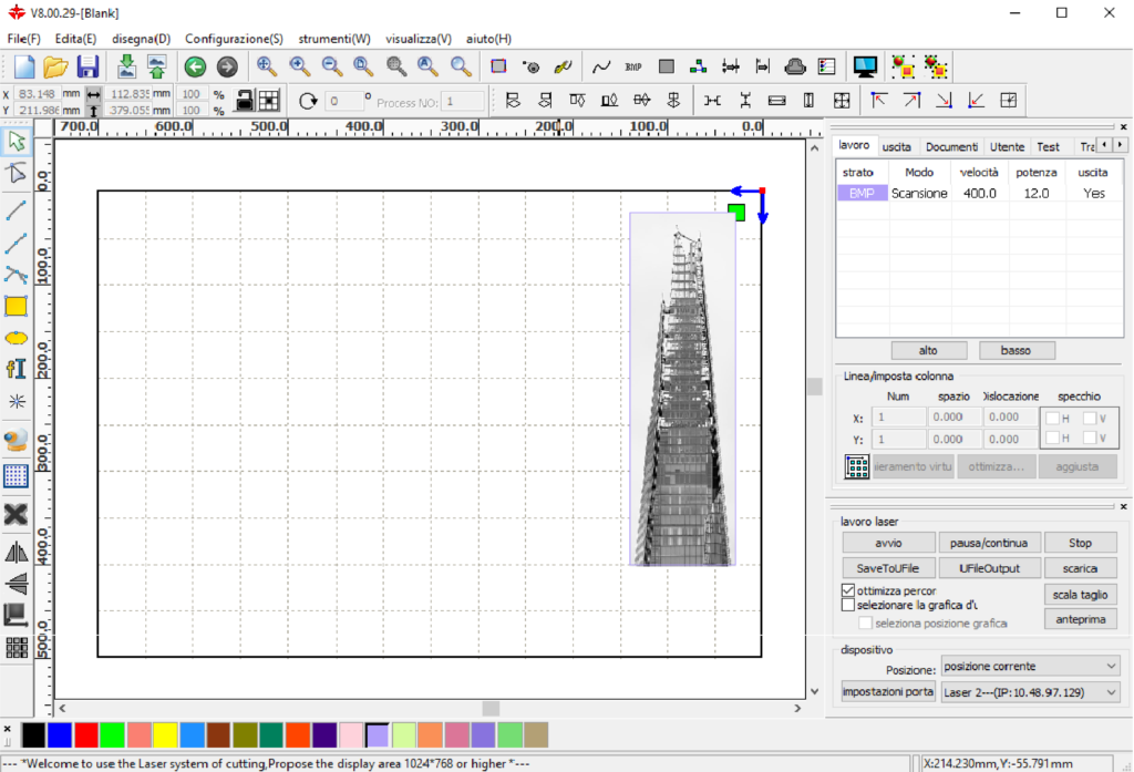
Using a similar procedure to paragraph c, it is possible to engrave on the surface of a sheet material a raster image (e.g. .jpg or .bmp) in greyscale, using the mode scansione. Import the image, following the steps in chapter 1, and change the parameters for scansione by following the steps in paragraph c.
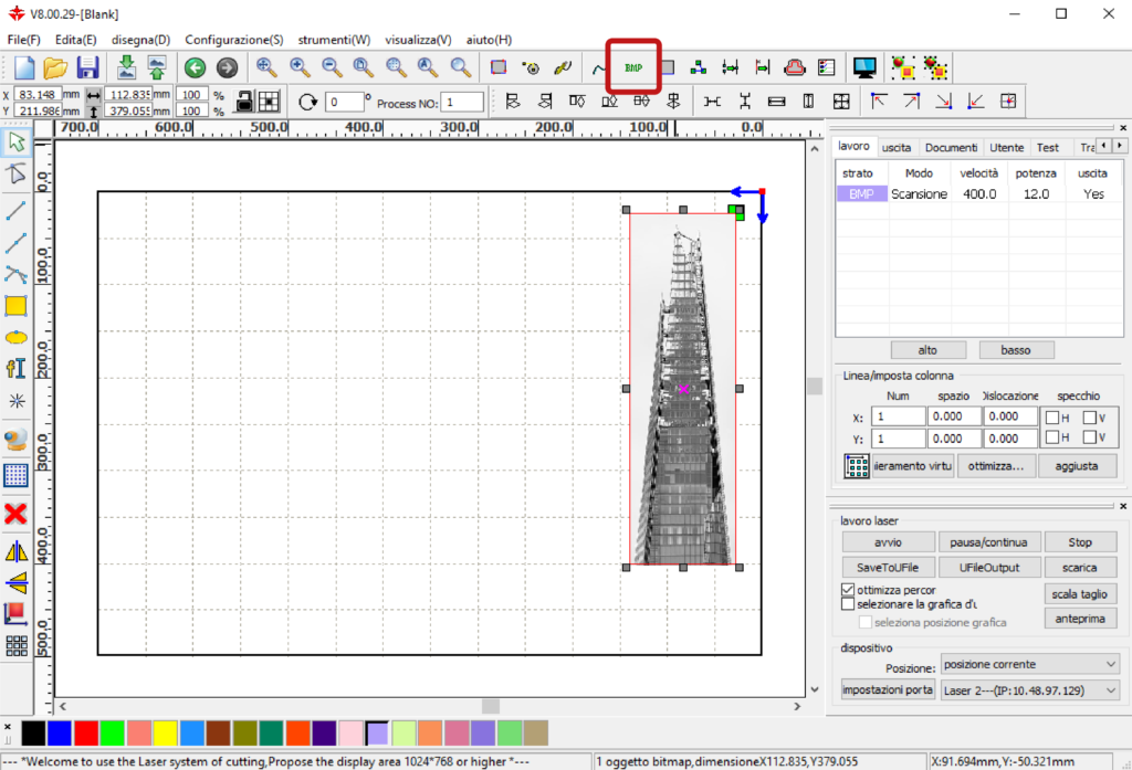
Click on the image to select it and choose the BMP button on the menu on top.
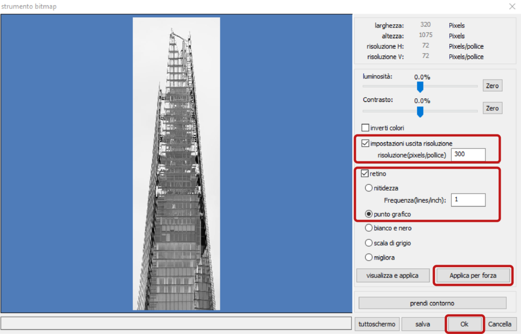
In the window strumento bitmap, activate the item impostazioni uscita risoluzione to the desired resolution and activate the item retino to then select the option punto grafico. Confirm the choices previously made in the window with the button Applica per forza (apply) and then with the Ok button.
14. advanced settings – staff operators only
a. how to determine the parameters for cutting, engraving and scanning
In general, to determine the best cutting and engraving parameters of a laser plotter for a given material of a given thickness, it is necessary to proceed by trial and error, looking for the highest speed, to reduce processing time, and the lowest power, to burn the material as little as possible, until you find the right balance between the two parameters.
In particular, the laser plotters that LaborA is equipped with, for cutting and engraving, can reach a maximum speed of 45 and a maximum power of 85. Therefore, to find the right balance of parameters, it is recommended to begin the tests with a speed of 45 and increase the power up to a maximum of 85, and once you get to this power start to decrease the speed.
To determine the best parameters for engravings of fillers in modalità di scansione and raster images, proceed in a similar way, taking into account that the plotters LaborA is equipped with, for scansione, can reach a maximum speed of 400 and a maximum power of 80.
As explained in chapter 4, the parameters for speed and power to cut and engrave materials are indicated in the window parametri libreria. After the tests for cutting and engraving it may be necessary to change the parameters of a material or add a new one by saving the settings in the window livello parametri.
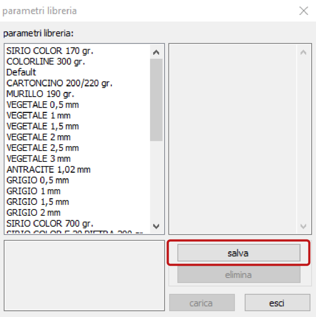
To add a new combination of speed and power parameters to cut a material, in the window parametri libreria click the button salva (save) and assign a nome parametro (parameter name).
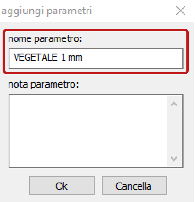
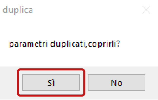
If the nome parametro that you want to assign already exists, it is possible to overwrite its parameters to update the material. In this case it is necessary to fill in the item nota parametro with the values for incisione and scansione already determined for that material or with new parameters considered more fitting.
The syntax to fill in the item nota parametro with the values is:
incisione = V: number – P: number – number
scansione = V: number – Pmax: number – number
The data in the window parametri libreria are automatically saved in the Param.lib file located in the folder (C:) > RDWorksV8. Each time you change parameters in the window parametri libreria, you must make a backup of the Param.lib file in order to have it available in case you need to reinstall RDWorks.
b. RDWorks in Chinese
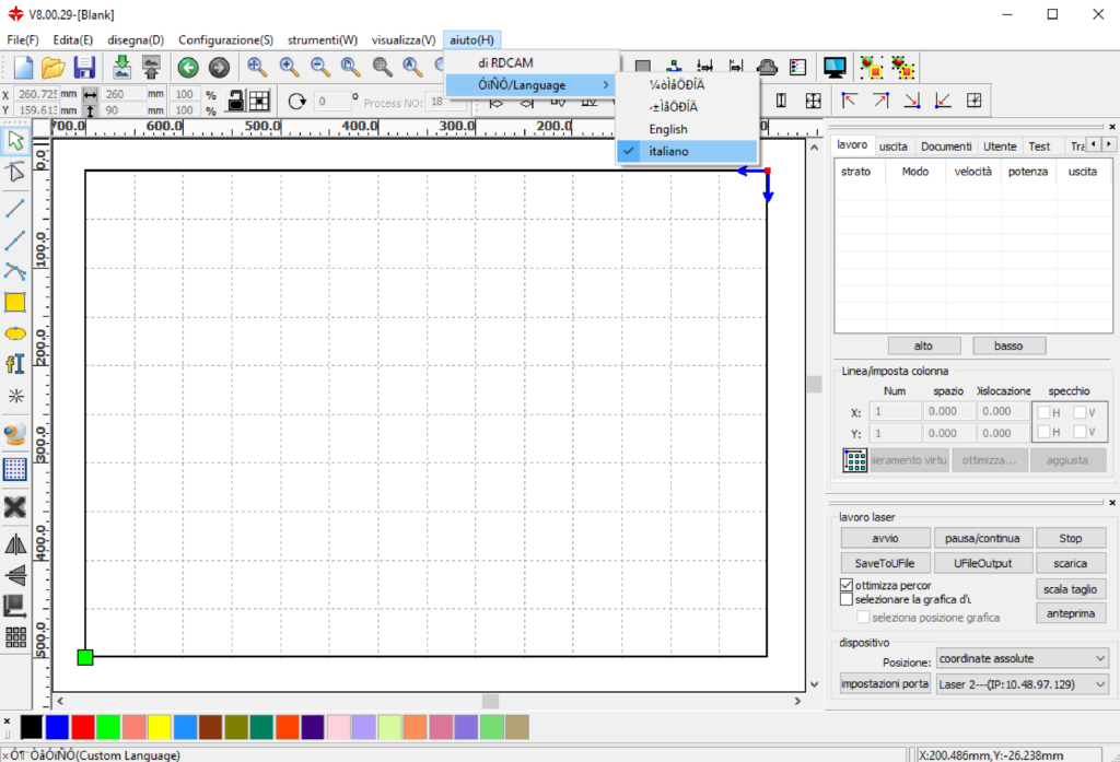
In the main menu bar at the top, which will appear in ideograms, click on the last item (H) > Language > Other > Italian.
c. PC does not communicate with the plotter
Communication Error appears. In the RDWorks software from the menu lavoro laser at the bottom right, in the section dispositivo, select impostazioni porta.
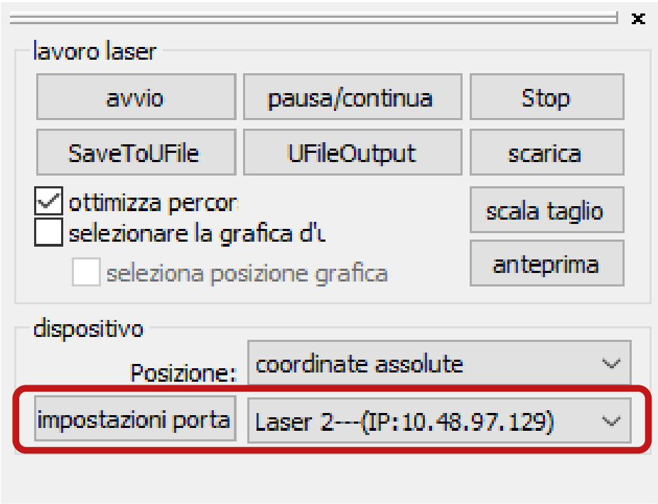
In the window that appears, tick the line of the machine in use and click the button elimina (delete).
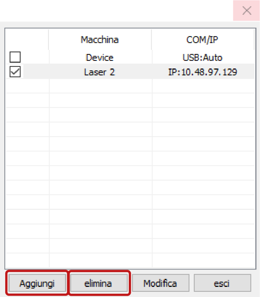
In the same window click the button Aggiungi (add) to open the window impostazioni porta where you can enter the IP of the plotter connected to the pc you are using.
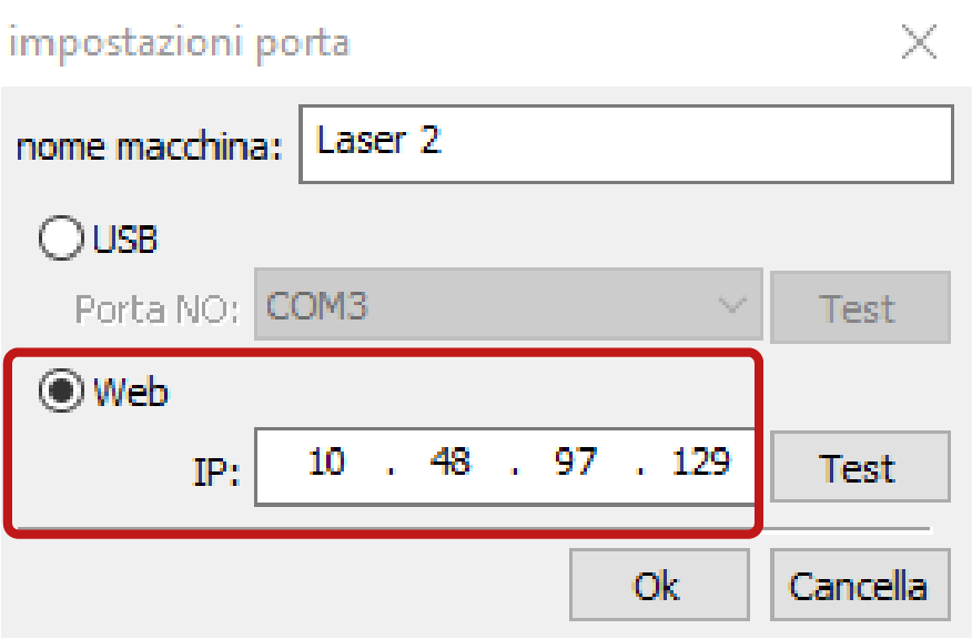
- Laser 1: IP 10-4-32-16 / Gateway 10-4-33-250
- Laser 2: IP 10-4-32-17 / Gateway 10-4-33-250
- Laser 3: IP 10-4-32-18 / Gateway 10-4-33-250
d. IP address of the plotter
To read the IP address of each plotter press Z/U > Config IP+ > Enter on the machine control panel. To return to the main menu use the Esc button.
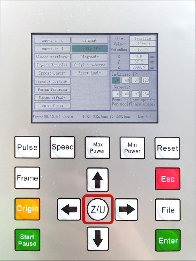
To change the IP address of each plotter press Z/U > Config IP+ > Enter and change the numbers in the boxes using the up and down arrows on the control panel and move between the boxes with the Z/U key. Confirm the compilation with the Enter key.
e. installing the RDWorks software
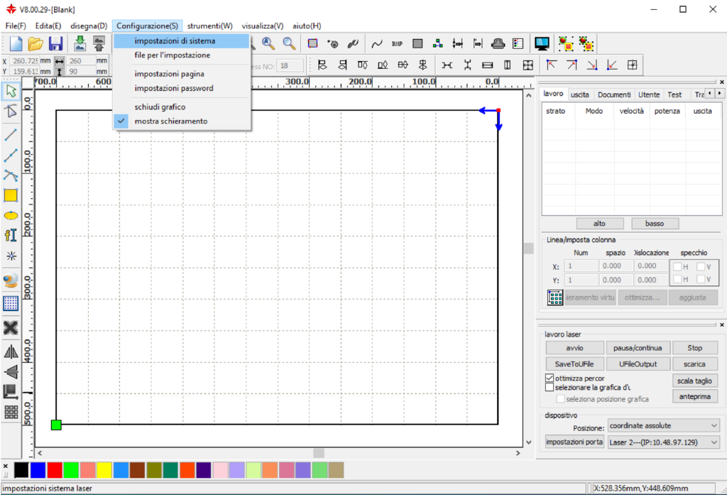
Set up the software as follows: in the main menu bar at the top select Configurazione (S) > impostazioni di sistema.
Tick limite di velocità piccolo cei and lettura (inversione intervalli).
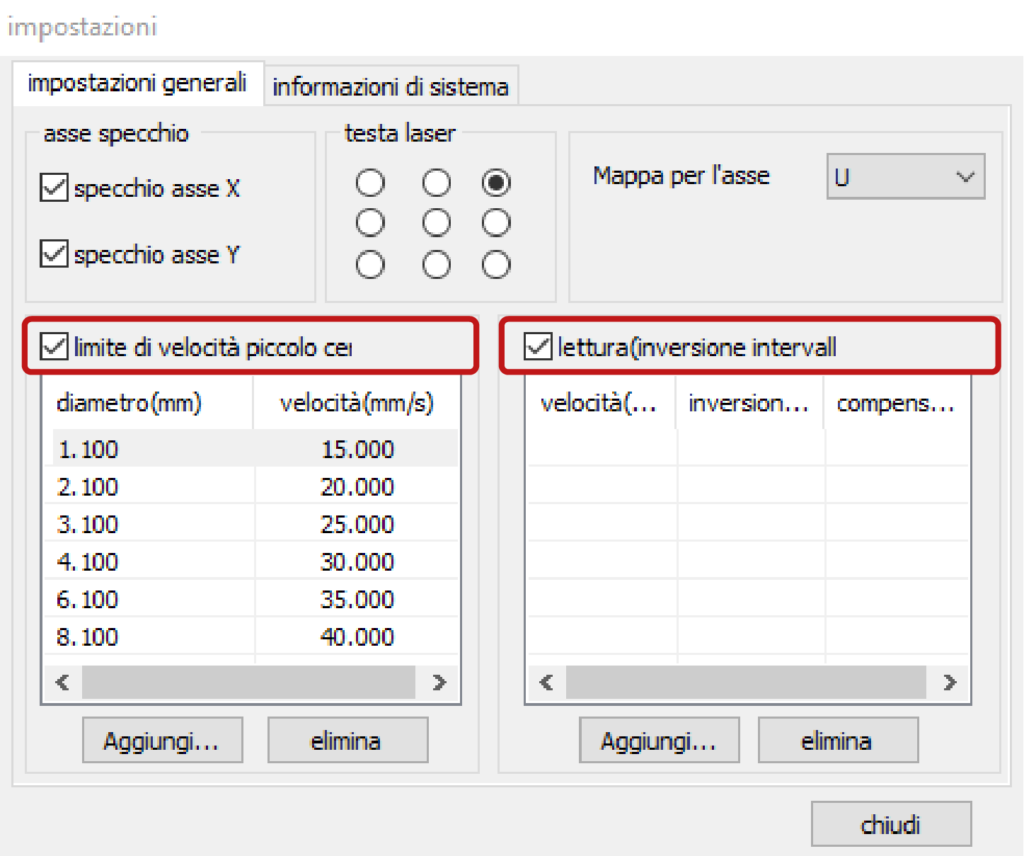
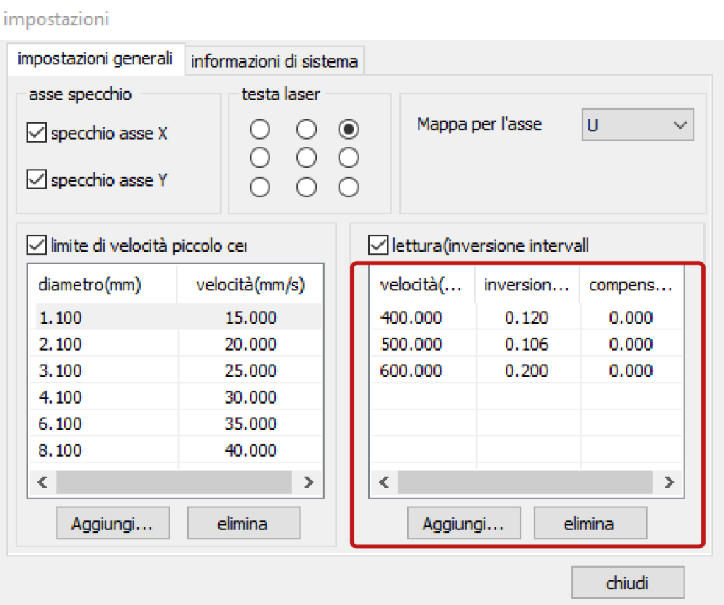
Then in the latter section click the button Aggiungi (add) and enter the following values of velocità (speed) and inversione (inversion) of the plotter connected to the pc you are using.
| velocità | inversione |
| 300.000 | 0.06 |
| 400.000 | 0.106 |
| 500.000 | 0.206 |
| 600.000 | 0.240 |
| velocità | inversione |
| 400.000 | 0.12 |
| 500.000 | 0.106 |
| 600.000 | 0.2 |
| velocità | inversione |
| 400.000 | 0.15 |
| 500.000 | 0.17 |
| 600.000 | 0.18 |
To import parametri libreria copy the backup file Param.lib in the folder (C:)> RDWorksV8.
The Param.lib file of each laser is stored in the folders Material Parameters_Laser 1, Material Parameters_Laser 2 and Material Parameters_Laser 3 located on: One Drive – Politecnico di Milano > Documentale ARES LaborA – Documenti > LaborA Fisico > Attrezzature > Lab. CNC > Taglio Laser.
f. error in the cutting order of the layers
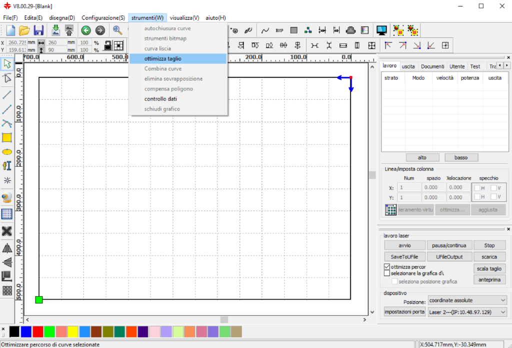
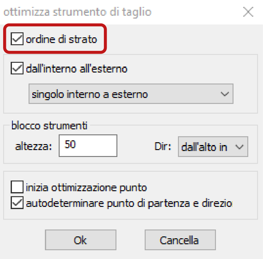
If the plotter does not follow the cutting order displayed in the window lavoro at the top right, in the main menu bar at the top select strumenti (W) (tools) > ottimizza strumento di taglio (optimize cutting tool) and check that the item ordine di strato (layer order) is ticked.
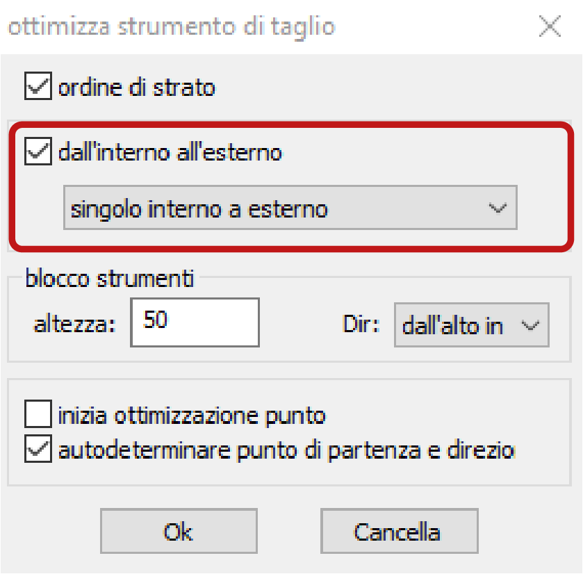
g. cutting order dall’interno all’esterno (from inside to outside)
In the case of cuts of geometries that have holes inside a perimeter, as in the case of facades with windows, it is advisable that the cut starts from the windows. If the perimeter is cut first, the piece might move due to the flow of compressed air that assists the cutting. In the main menu bar at the top select strumenti (W) (tools) > ottimizza taglio (optimize cut) and tick the item dall’interno all’esterno (from inside to outside).
h. shortening engraving times for fillers and raster images
Making scans placed at the extremities of the working area can lead to long processing times, but it is possible to significantly reduce them.
In the top-right panel in the section lavoro, double-click on the layer that contains the scans to open the related window livello parametri and activate the item uscita indipendente (independent output).
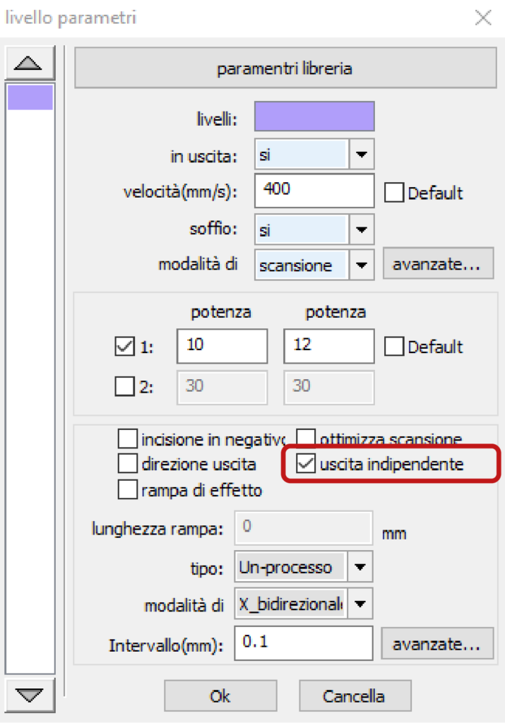
In this way the machine will carry out the scans independently: it will realise the first on in full before moving to the next one.
To check the processing times, refer to chapter 6. checking cutting times.
i. reading machine work time
To read the working time of the plotter, turn on the machine and on the computer connected to it select Configurazione(F) > Impostazioni di sistema from the main menu of the RDWorks software.
In the window impostazioni, choose the section informazioni di sistema and insert the password: RD8888 in the field fornitore password. Then confirm by clicking on the Input button.
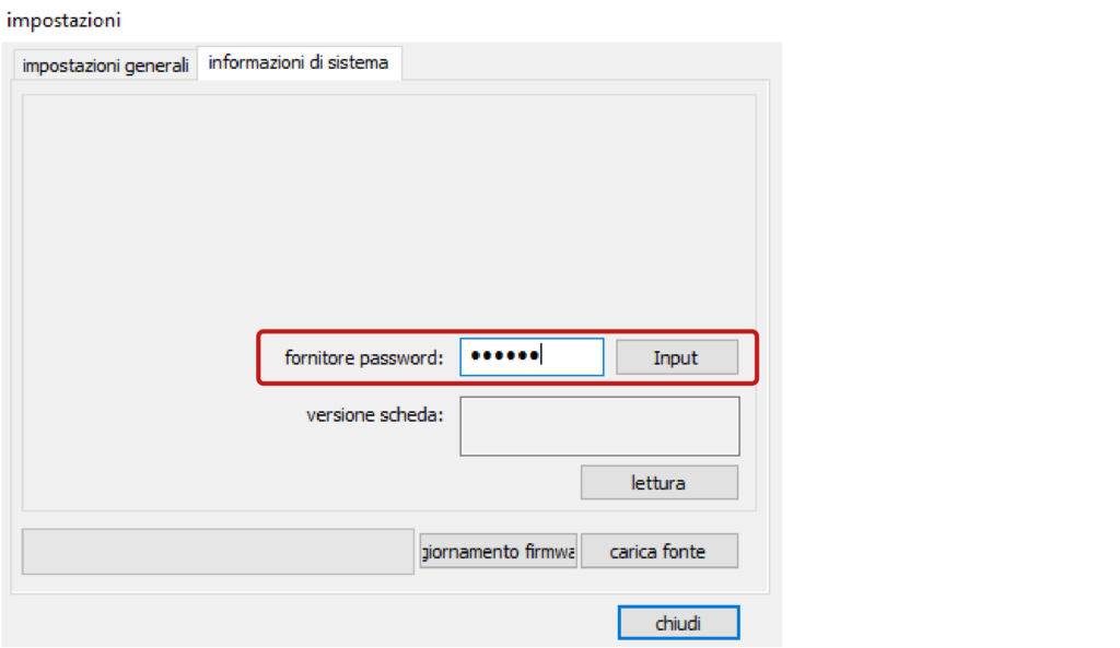
After the window is updated, click on the button lettura (read)to view the data.
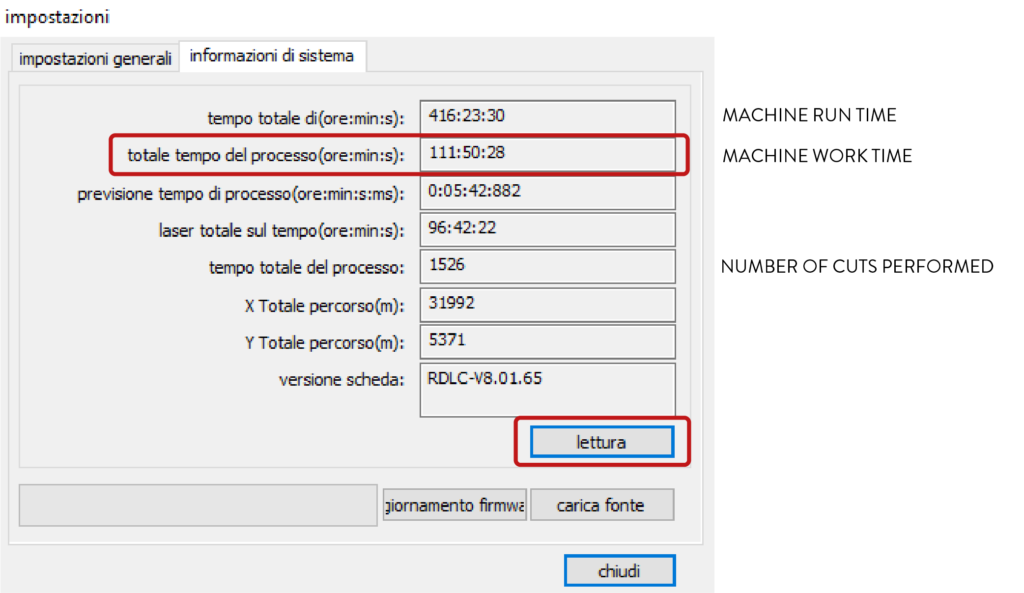
The machine work time corresponds to the second item totale tempo del processo(ore:min:s):
15. checklist for operators
a. check before cutting
- the number of sheets to be cut must coincide with the number noted in the appointment;
- the file must contain the two frames so that it is easier to check if the pieces have been drawn in the correct scale and on a single plane with Z zero;
- the minimum distance of the pieces from the inner frame and between the pieces to be cut must always be respected;
- always make a small cutting test to verify that the parameters of the library are appropriate to that specific sheet of material, especially in the case of plastics to verify their laserability;
- request confirmation from students of the accuracy of the drawings once they are imported into RDWorks before making the cuts, in order to be sure that the program has correctly read all the items saved in the .dxf file;
- if tests have to be cut, place them between the programmed cuts and make only small samples;
- in case you have to cut cardboard with a striped texture, the pieces to be cut must be positioned in the same way, otherwise the orientation of the stripes will change, for example on the facades;
- if you need to cut drawings with dense lines, backgrounds or raster images, always check the processing times by previewing them to schedule appointments.
b. procedures not to be performed
Unless specifically indicated and confirmed by the reference tutor, the following operations shall not be carried out:
- cutting or engraving of unusual materials;
- laser cuts on white or light-coloured cardboard;
- laser cutting of topography lines that are normally made with blade cutting;
- cutting simple shapes such as rectangles;
- cutting shapes almost as big as the frame, such as, for example, the upper lining of a base with a simple hole;
- cutting of the same shape repeated several times which would presumably create a volume made of overlapping layers;
- cutting pieces with geometries thinner than the thickness of the material being cut;
- cutting pieces that are too small and would be sucked by the panel, if not bound by cutting breaks;
- cutting of many thin grid elements with holes of about 1 mm, railings or brise soleil, if to be realized on cardboard other than 200/360 gr/sqm;
- cutting of methacrylate more than 1 mm thick;
- cutting of thin rods;
- cutting shapes of men, trees, cars, bicycles, etc.;
- engraving of urban plans, facade drawings, for folding or for placing pieces both in urban and architectural models;
- engravings on plastic of very detailed elements such as doors or windows;
- raster engravings.
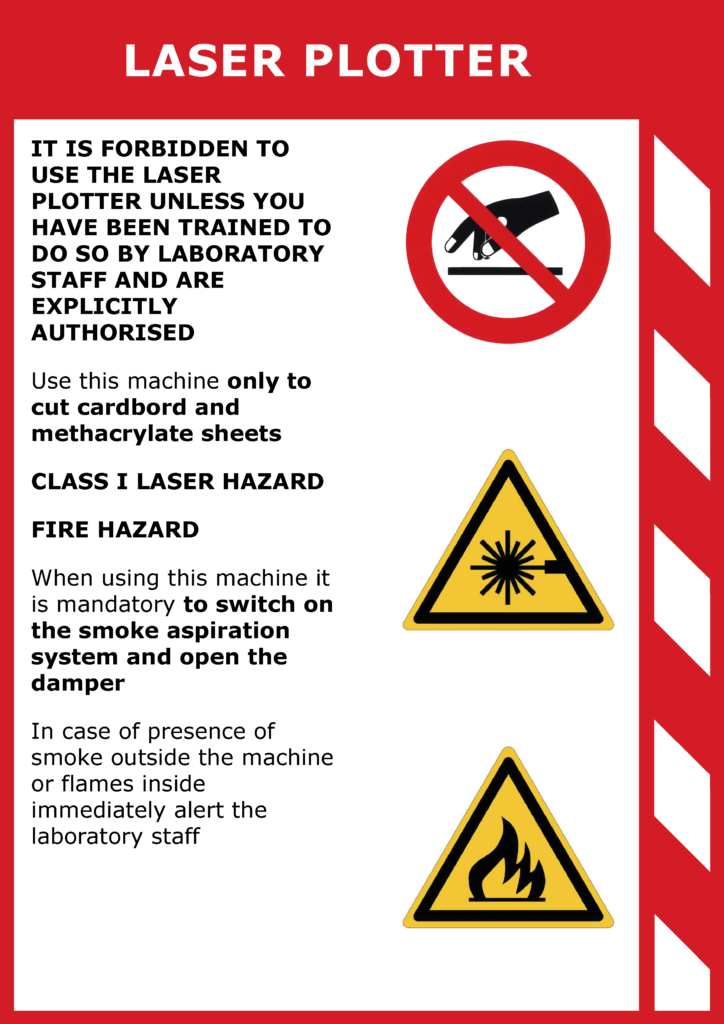
16. prohibitions and regulations
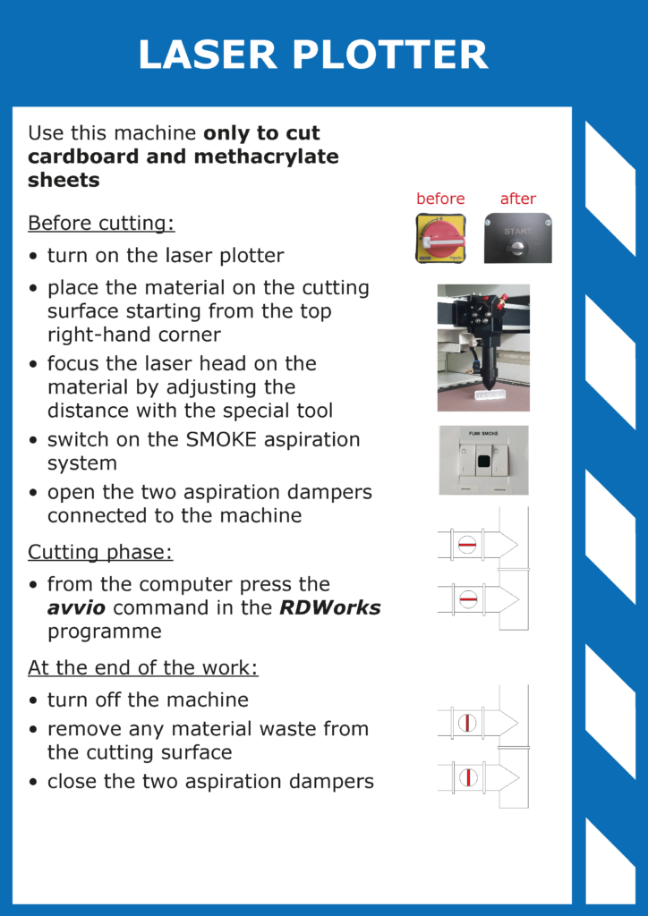
17. machine sheets