sunguitar
Rookie Solder Flinger

Posts: 12
Likes: 0
|
Post by sunguitar on Aug 25, 2018 18:52:33 GMT -5
Hi everybody, this is my first post in this great forum. I need help to wire my HSS standard mex strat to get the switch options I want. What I have now is the stock HSS, the only mod done is I have switched the stock neck to a Dimarzio HS3 (stacked sc). My stock fender HSS wiring is here in pdf
1 - Bridge HB 2 - Bridge HB N + Mid (the HB auto splits so the coil closest to the Mid pickup is active) 3 - Mid 4 - Mid + Neck 5 - Neck What I want is this: Keep everything the same as stock switching above so I have access to the 5 stock sounds. pot 1 - Volume pot pot 2 - add a DPDT pot working as master tone, and to get the HB in parallel mode when pulled up. pot 3 - add a no-load Blender pot to add neck/bridge depending on switch position. When DPTD pot is pulled up I want this:1 - Bridge HB in parallel 2 - Bridge HB in parallel + Mid 3 - Mid 4 - Mid + Neck 5 - Neck When blender pot is used when DPTD switch is up I want this:1 - Bridge HB in parallel + Blend in Neck 2 - Bridge HB in parallel + Mid + Blend in Neck 3 - Mid 4 - Mid + Neck + Blend in Bridge HB in parallel 5 - Neck + Blend in Bridge HB in parallel When blender pot is used when DPTD switch is down I want this:1 - Bridge HB + Blend in Neck 2 - Bridge HB N + Mid + Blend in Neck 3 - Mid 4 - Mid + Neck + Blend in Bridge HB - (if possible I would like to blend in the Bridge HB N instead of the full HB) 5 - Neck + Blend in Bridge HB - (if possible I would like to blend in the Bridge HB N instead of the full HB) I have searched for a long time online but can't find a wiring like this and I obviously can't figure the wiring out myself. If some expert here could help me with an easy to read wiring image schematic of this setup I would be so happy and grateful. The fender HB I have is Fender color coded guitarelectronics.com/guitar-wiring-resources/humbucker-wire-color-codes/I have soldered a few times before but I need to follow a wiring schematic and I have a no-load pot and a DPDT pot ready to go. There are separate instructions for HB in parallel online and Blender mods like this from Breja toneworks Blender Strat Wiring DIY but I've never seen them combined to an HSS strat before. Cheers! |
|
|
|
Post by thetragichero on Aug 25, 2018 20:53:56 GMT -5
hello and welcome to the nut house - it's like the psych ward but with more solder and they don't take away your shoelaces!
to be honest, i worked all day in the sun so it's a minor miracle i am able to form reasonably coherent sentences. but one of the guys will be around to help you further
quick glance it doesn't seem too impossible with a super switch
stick around!
|
|
sunguitar
Rookie Solder Flinger
Posts: 12
Likes: 0
|
Post by sunguitar on Aug 25, 2018 21:01:31 GMT -5
Thanks, yes this place sure has some incredible knowledge. I hope I don't need a super switch for this wiring because I don't have one and I would prefer to keep the original switch.
What switch options would I lose or not be possible if I don't use a super switch?
Most important options for me is getting the HB in parallel with the DPDT switch. Also having the option to blend in the neck with HB parallel and blend neck with HB N coil.
Basically get the HB in parallel and be able to use as many blend options as possible.
This intricate wiring I found on this forum by JohnH doesn't require a super switch Strat SSM2 - HSS with 15 sounds and one dpdt
|
|
|
|
Post by reTrEaD on Aug 25, 2018 23:13:25 GMT -5
I went to a family party today so I'm a bit *ahem* "unfocused" at the moment but what you're asking for sounds rather straightforward.
Run of the mill Strat switching: 5 - Neck
4 - Mid + Neck
3 - Mid
2 - Bridge + Mid
1 - Bridge Master Volume and Master Tone (no need to use the other half of the 5-way to select tone control) DPDT Series/Parallel switch for Bridge HB North coil stacked over South coil in series mode Auto-split in positions 5~2 accomplished with the other half of the 5-way
connects the North (-) to ground in positions 5~2
redundant in parallel mode
shunts the South coil in series mode, leaving just the North coil in use.
Bridge-to-Neck Blender connects between bridge lug and neck lug of pickup selector
audio taper no-load pot
clockwise = no connection
rotate counterclockwise to blend in.
|
|
sunguitar
Rookie Solder Flinger
Posts: 12
Likes: 0
|
Post by sunguitar on Aug 26, 2018 13:07:10 GMT -5
Thanks.
So can the blender knob only blend the neck or full HB, not the HB N (inner coil) or HB in parallel?
I guess I'm able to preserve the stock HB auto-split in pos 2 when I don't use blender or DPDT.
I'm glad I don't need a super switch for this to work.
I don't have the skill to figure the whole wiring schematic out myself, I need to see an image.
I can't find a schematic for this online, please post a link if there is one.
Is there a blank wiring template image for HSS I can use to try and draw the wiring to and post here?
That would require some revisions since I'm a novice at this.
|
|
|
|
Post by reTrEaD on Aug 26, 2018 13:40:52 GMT -5
So can the blender knob only blend the neck or full HB, not the HB N (inner coil) or HB in parallel? Not true.
The position of the series/parallel switch and the position of the 5-Way will determine what you get from the Bridge pickup, whether it's selected directly or by "blending in". In positions 5~2 of the 5-way, with the S/P switch in Series mode, the Bridge will be just North coil only. Position 3 is irrelevant since it's Middle only. But in positions 2 ,4, and 5, you'll get exactly what you said you wanted in your OP. Likewise when in Parallel mode, all inclusions of the Bridge pickup will have both bridge coils in parallel. I don't have the skill to figure the whole wiring schematic out myself, I need to see an image. I can't find a schematic for this online, please post a link if there is one. Is there a blank wiring template image for HSS I can use to try and draw the wiring to and post here? That would require some revisions since I'm a novice at this. I don't have the time to do a full workup on a diagram but this seems like a good community project. We'll invite others who might like to do some drawing. The first step would be to draw the DPDT as a S/P switch for the Bridge pickup. Then add in half of the 5-way to do the auto-split in positions 5~2 when the S/P is in series mode. When we get that far, the rest is a cakewalk. |
|
|
|
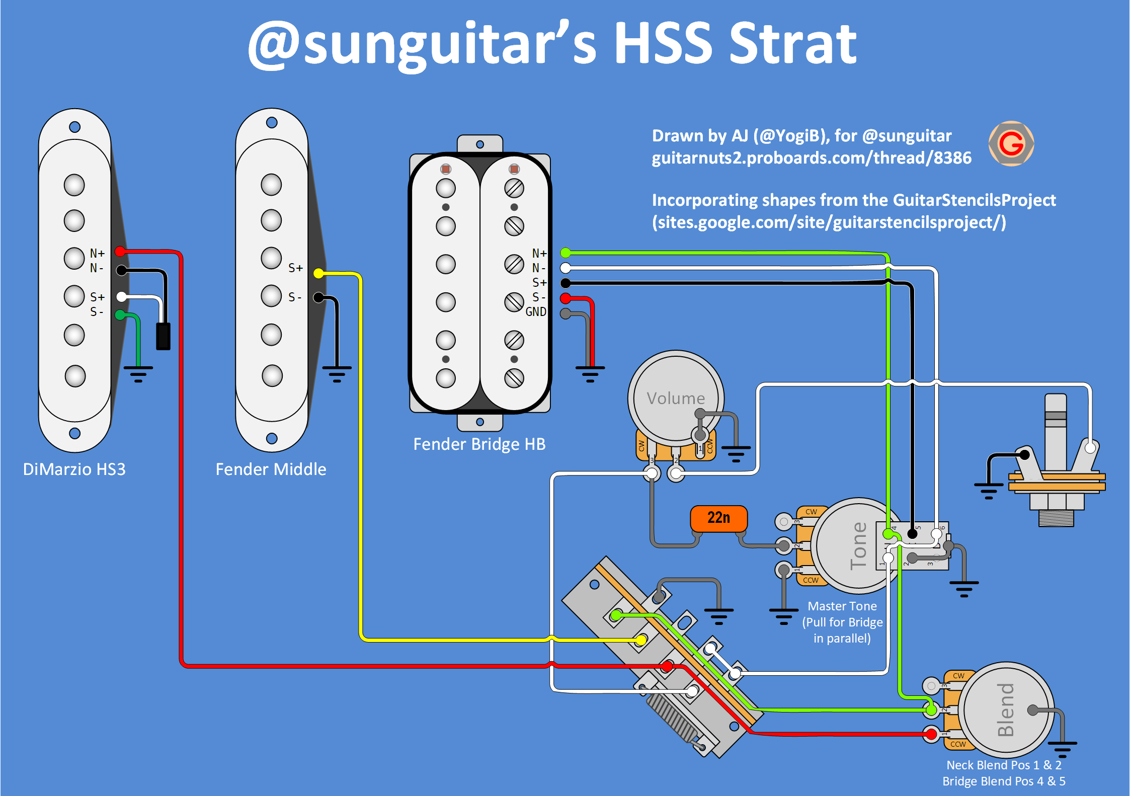
Post by Yogi B on Aug 26, 2018 19:23:55 GMT -5
I don't have the time to do a full workup on a diagram but this seems like a good community project. We'll invite others who might like to do some drawing. Hope you don't mind if I invite myself... I think I have the polarities correct, but a look over wouldn't go amiss. |
|
sunguitar
Rookie Solder Flinger
Posts: 12
Likes: 0
|
Post by sunguitar on Aug 26, 2018 20:04:56 GMT -5
Thank you so much Yogi B for taking the time to do the schematics, it looks fantastic!
That guitar stencils project really makes it look pro.
I had started drawing my own schematic but 90% was wrong and not a single wire on the DPDT switch was correct, haha.
I'm so excited to get going right away but I'll let all you experts have a look at it before I start soldering tomorrow.
Thank you all for helping out, this place rocks!
|
|
|
|
Post by reTrEaD on Aug 26, 2018 20:31:45 GMT -5
Hope you don't mind if I invite myself... I don't mind and I'm sure sunguitar will be one happy camper. The switch logic looks right. No mention of the trem ground but that's a no-brainer. |
|
|
|
Post by newey on Aug 26, 2018 21:04:04 GMT -5
I'm not doubting YogiB's diagram, and perhaps I'm just being my usual obtund self, but in position 4, won't the blend knob be blending both the neck and mid into the bridge?
|
|
|
|
Post by Yogi B on Aug 27, 2018 11:08:52 GMT -5
That guitar stencils project really makes it look pro. Apart from the slightly elliptical pole pieces on the single coils, and the different widths between the height adjustment screw holes (admittedly there's a chance that's true to life, but nonetheless looks odd). Doing a "tweaked" (most likely redone from scratch) version of single coils is next on my list after the humbucker, but I've not got around to quite finishing that yet. I'm not doubting YogiB's diagram, and perhaps I'm just being my usual obtund self I'm not sure someone "obtund" would know the meaning of that word, however you did just use it, a verb, as an adjective -- perhaps you meant obtuse? Or maybe you did that on purpose to overemphasise your point, in order to make clearer that it was intended to have a hint sarcasm? Who knows? In position four, as defined by sunguitar, we have the neck and middle in parallel selected by default, blending in the bridge additionally, also in parallel. So 1/ 2 yes, but that's what we want anyway! Alternatively, I thought maybe you meant the other position four (i.e. position two), but I can't see what you'd mean there either. |
|
sunguitar
Rookie Solder Flinger
Posts: 12
Likes: 0
|
Post by sunguitar on Aug 27, 2018 11:49:16 GMT -5
I haven't started soldering yet.
Before falling asleep last night I thought a lot about the schematic and it occured to me that I would like to have a no-load tone pot.
I previously had thought I couldn't do that to a DPDT pot but I was wrong, it worked just like on normal pots by scraping off the carbon track at the end.
Then I realized I could have the no-load to function as a Blender in the DPDT pot.
Having access to both parallel DPDT and blender in one pot means I would have much easier playing access functionality of the pots.
I very rarely use the tone pot so why not have it in pos 3 and have all the business in the first two pots.
I hope this little alteration of Yogi B's schematic doesn't change things too much and will have all switching options intact.
Revision 1:
pot 1 - Volume
pot 2 - DPDT & Blender
pot 3 - Master tone
Tone lug 2 goes to Vol lug 1 (with 22n)
Tone lug 3 goes to ground
Wires going in to the DPDT are unchanged.
Green DPDT goes out to lug 2 of Blender, and that green lug 2 goes out to the switch.
Blender lug 3 Red goes to the switch.
Please let me know if the above is correct and will work.
|
|
|
|
Post by Yogi B on Aug 27, 2018 16:44:50 GMT -5
Then I realized I could have the no-load to function as a Blender in the DPDT pot. Having access to both parallel DPDT and blender in one pot means I would have much easier playing access functionality of the pots. I very rarely use the tone pot so why not have it in pos 3 and have all the business in the first two pots. I hope this little alteration of Yogi B's schematic doesn't change things too much and will have all switching options intact. Basically you'd wire it as is but mentally transplant the DPDT onto the body of the Blend pot, and swap it's physical location with the tone pot. Looks like you have your 1s & 3s swapped. The most common notation is that with the pot shaft upwards and the terminals facing towards you, the terminals are labelled left-to-right: 1, 2, 3. That is, when the control is turned to "10" (fully clockwise when viewed from the front of the guitar) terminal 2 should have close to zero resistance to terminal 3 and its rated resistance (plus/minus tolerance) to terminal 1. Vice-Versa when turned to "0" (or "1" on Fenders, fully counter-clockwise). Though there's always others who (unhelpfully) impose there own standards. (An exception to the above are reverse log taper pots, which tend to be labelled in the reverse, but that's not relevant here.) |
|
sunguitar
Rookie Solder Flinger
Posts: 12
Likes: 0
|
Post by sunguitar on Aug 27, 2018 17:03:49 GMT -5
Thanks for the correction, what was I thinking.
When I look closer on your schematic image each lug is numbered!
Now with that fixed does it look correct now?
Revision 1:
pot 1 - Volume
pot 2 - DPDT & Blender
pot 3 - Master tone
Tone lug 2 goes to Vol lug 3 (with 22n)
Tone lug 1 goes to ground
Wires going in to the DPDT are unchanged.
Green DPDT goes out to lug 2 of Blender, and that green lug 2 goes out to the switch.
Blender lug 1 Red goes to the switch.
|
|
|
|
Post by Yogi B on Aug 27, 2018 17:15:50 GMT -5
When I look closer on your schematic image each lug is numbered! To be fair they are really quite small in the overall scheme of things.As far as I can see, yes. |
|
sunguitar
Rookie Solder Flinger
Posts: 12
Likes: 0
|
Post by sunguitar on Aug 27, 2018 17:23:33 GMT -5
Great!
Your schematic is easy to follow and I hope to be steady on the hand and not make any soldering mistakes.
I have a question about the DPDT nr 2 wire going to ground.
In your schematic it looks like it is soldered two times.
I'm guessing that the purpose of that little piece of metal sticking out on top of the DPDT switch above the six lugs is to have an easy place to ground to.
This is going to be fun!
|
|
|
|
Post by Yogi B on Aug 27, 2018 17:58:31 GMT -5
I'm guessing that the purpose of that little piece of metal sticking out on top of the DPDT switch above the six lugs is to have an easy place to ground to. Correct. Though it probably primarily originates from DPDT pots designed for use mounted to PCBs, it does offer a near ideal location for 'regular' soldering. With the switch itself taking up the majority of the back of the pot (the most commonly used grounding point), we need an alternate location. The entire base of the switch itself isn't really viable as the chassis works a bit too well as a heat sink making it possible to melt to the switch's internals, if you're not overly careful, before getting the area hot enough to accept solder. The thin tang reduces this unwanted heat transfer making soldering easier. (I've also seen people suggest using the side of the pot body instead, but it's something I've never tried myself.) |
|
sunguitar
Rookie Solder Flinger
Posts: 12
Likes: 0
|
Post by sunguitar on Aug 30, 2018 16:49:08 GMT -5
In the middle of soldering I decided to replace the neck HS3 with a Dimarzio Area 58 and I assume it has the same 4 wire code as my previous HS3. What I noticed is that in my previous wiring I had the HS3 green going to the switch and red going to the ground (black & white taped together).
That gave me the expected sound in 4th position mid+neck.
I have now tested the new wiring (Area 58 neck: red going to switch and green to ground) and something is not right.
In all positions where the neck is mixed or blended in with other pickups I get an extremely thin sound (out of phase?).
The neck sounds good on its own in pos 5 and the other pickups sound good (HB in parallel is very nice).
What causes this and how do I fix it?
Should I wire it like I previously had with my HS3 (Green going to the switch and red going to the ground)?
On this HSS strat I assume the stock mid pickup is rwrp.
|
|
|
|
Post by thetragichero on Aug 30, 2018 21:07:54 GMT -5
thin trebly sound is likely out of phase. swap hot and ground wires of the area 58 (i had an area 67 and it was a great pickup. if the 58 is anything like the 67 you'll enjoy) and give it a shot
|
|
sunguitar
Rookie Solder Flinger
Posts: 12
Likes: 0
|
Post by sunguitar on Aug 30, 2018 22:06:27 GMT -5
That sounds like a good idea, I will do that and see if it helps.
But aren't the wires supposed to be this way they are now?
The HS3 will find a good place in another strat for the yngwie moments.
I wanted a more traditional strat sound for this one and the Area 58 sounds fantastic on its own, first time I try area pickups.
I've gotten the three Area 58, 67 and 61 and will likely try them all in this guitar. I was a bit worried putting the 67 in the neck since I've read that sometimes the 67 can be rwrp. Is there any info on the pickup if they are rwrp or can I test it with a multimeter?
|
|
|
|
Post by newey on Aug 30, 2018 22:30:21 GMT -5
Most aftermarket single-coil pickups are sold in either RWRP or "normal" versions. Often the wire color for the RWRP pickup will be different, making it easy to ID the RWRP one (if one has a matched set of three).
But you can easily test for a RWRP pup, provided the pickups are not mounted in the guitar- no multimeter necessary! No manufacturer makes a pickup that is reverse polarity, but normally wound (or normal polarity, reverse wound, for that matter); it wouldn't be hum-cancelling and in phase with the other pickups unless it is both reverse wound and reverse polarity.
So, if two pickups are of opposite magnetic polarity, they will be reverse wound as well. So, all you need to test is the magnetic polarity. "Opposites attract", as the saying goes, so if you hold two pickups magnet-to-magnet and they repel, they are of the same polarity; if they attract, they are reveres with respect to each other. In a set of three, the "odd man out" is the RWRP one.
|
|
|
|
Post by thetragichero on Aug 31, 2018 7:26:00 GMT -5
That sounds like a good idea, I will do that and see if it helps. But aren't the wires supposed to be this way they are now? The HS3 will find a good place in another strat for the yngwie moments. I wanted a more traditional strat sound for this one and the Area 58 sounds fantastic on its own, first time I try area pickups. I've gotten the three Area 58, 67 and 61 and will likely try them all in this guitar. I was a bit worried putting the 67 in the neck since I've read that sometimes the 67 can be rwrp. Is there any info on the pickup if they are rwrp or can I test it with a multimeter? those dimarzio areas are all 'stacked humbucker' single coils (dimarzio calls them virtual vintage). that's why they have the two extra wires that are soldered and maybe heat shrunk together. in my brief experimenting, don't even bother trying to use the series connect wire to split them: sounds about the same. so with those it's even easier because all you're caring about is the system polarity of each pickup. swap them leads, boyo! |
|
|
|
Post by Yogi B on Aug 31, 2018 11:35:27 GMT -5
Most aftermarket single-coil pickups are sold in either RWRP or "normal" versions. Often the wire color for the RWRP pickup will be different, making it easy to ID the RWRP one (if one has a matched set of three). As trag' points out DiMarzio Areas are not true single coils but rather stacked humbucker types so this doesn't apply, no need to do anything RWRP if the pickups are already hum cancelling on their own! Not a single manufacturer no, but lets say one manufacturer winds their north-up coils clockwise and south-up counter-clockwise, there's nothing to stop another manufacturer from doing the opposite. Is that what we have here: Fender and DiMarzio using conflicting winding directions? That sounds like a good idea, I will do that and see if it helps. But aren't the wires supposed to be this way they are now? Yep should do, I drew them the way round I did because that's the way the DiMarzio Area / Injectors that I have are wired, and it appears to be the standard wiring. However I didn't consider that it mightn't play nice with the Fenders, sorry. In my brief experimenting, don't even bother trying to use the series connect wire to split them: sounds about the same. There could be an argument for splitting one to achieve hum cancelling with a regular single coil, for instance in position 4 of this layout, which should be possible with a super/megaswitch, then we'd have to consider if that would actually be hum cancelling or whether the we'd need the middle pickup to be RWRP of what it currently is, and maybe swapping it for another (maybe the original neck pickup). Another thing that's expressly not recommended for stacked DiMarzios is parallel wiring their coils. |
|
sunguitar
Rookie Solder Flinger
Posts: 12
Likes: 0
|
Post by sunguitar on Aug 31, 2018 16:16:30 GMT -5
Switching the red and green wires did the trick! I'm so happy and thankful for all your help, I could never have done all this by myself. Now I have a very versatile HSS tone machine that sounds fantastic. What I'm most impressed by is the blender knob, it offers very telecasterish tones which is exactly what I wanted. The HS3 is great with low to high overdrive or distortion but was a bit sterile sounding for clean sounds. The Area 58 can do it all from vintage bell cleans, blues to yngwie and with a bit more attitude than the HS3. It has zero hum and is more silent than the HB. Here are some more questions: I put in a 500k linear DPDT pot to function as parallel switch and blender knob. 1 - Does the value of the pot affect the sound at all for the no-load blender knob or DPDT, will a 250k sound the same as a 500k pot? 2 - Can a no-load tone pot value be reduced by adding a resistor, like a normal pot can going from 500 to 250 with a resistor? 3 - Can I measure the value of an installed volume pot with my multimeter, if so how? I can measure the installed tone pots on the lugs but not the volume pots installed in my guitars. 4 - In an SSS guitar, will a pos 1 bridge + blender max neck sound identical to pos 5 neck + blender max bridge? In my previous stock wiring I had diconnected (desoldered) the tone knobs to get more highs because the guitar was a bit dull sounding. During this new wiring I measured the 250k tone pot in the middle and it was only 185k. That is more than the 20% tolerance I think these Fender pots have. I decided to increase the value of it to 300k by scraping the inner and outer sides of the carbon track to reduce the taper evenly, and also making it a no-load pot by cutting the carbon track at the end. So now I have a very versatile and brighter tone pot. Do you think that the scraped carbon track will affect the feel of the taper? I tried to do it as even as I could.
I learned it from this video, "How to Increase a Pot's Resistance Value" I assume that in the no-load tone position that I now have, it should sound the same as when I had the tone pots disconnected. |
|
|
|
Post by newey on Sept 1, 2018 7:42:19 GMT -5
Not sure what you mean about the "feel of the taper". It shouldn't affect the feel of the operation of the knob, if that's what you mean. As for the sound, the difference between 300K and 250K is likely to be very subtle. I rewired an old guitar, replacing 300K pots with 250K (since I had them in the parts bin) and couldn't tell any difference, but my aging ears aren't what they once were, and the treble is the first thing to go.
Yes, assuming the resistive track has been scraped properly.
|
|
|
|
Post by reTrEaD on Sept 1, 2018 11:17:31 GMT -5
Here are some more questions: I put in a 500k linear DPDT pot to function as parallel switch and blender knob. 1 - Does the value of the pot affect the sound at all for the no-load blender knob or DPDT, will a 250k sound the same as a 500k pot? 2 - Can a no-load tone pot value be reduced by adding a resistor, like a normal pot can going from 500 to 250 with a resistor? 3 - Can I measure the value of an installed volume pot with my multimeter, if so how? I can measure the installed tone pots on the lugs but not the volume pots installed in my guitars. 4 - In an SSS guitar, will a pos 1 bridge + blender max neck sound identical to pos 5 neck + blender max bridge? Here are my opinions: - With the control fully clockwise, a 250k no-load pot will sound exactly the same as a 500k no-load pot.
- Adding a resistor in parallel with a no-load pot defeats the purpose. I wouldn't.
- You can estimate the value of volume pot with some careful measurements and a bit of math. However if you have a parallel treble-bleed network with unknown resistor value, this will severely complicate the matter. The short version is: Measure the resistance between tip and jack of the output jack. (You can do this without even taking the cover off the control cavity.) Rotate the volume pot until you get maximum resistance displayed on your meter. This value will be
1/2 1/4 the total resistance of the volume pot + DC resistance of whatever pickup(s) is/are selected, so multiply that number by two four then subtract the pickup resistance. If you have a treble-bleed network (which includes a parallel resistor) that will complicate the bejeezus out of the math. For additional information: Discerning Strat-Type Resistances
- If by "+ blender max" you mean the position on the blender where the resistance is zero and the maximum possible contribution of the 'blended' pickup is added, then theoretically yes. If that position of the blender is actually zero resistance, the blended pickup will be directly in parallel with the selected pickup.
|
|
sunguitar
Rookie Solder Flinger
Posts: 12
Likes: 0
|
Post by sunguitar on Sept 1, 2018 18:43:49 GMT -5
Thanks for explaining.
I plugged in a cable and measured the tip and the lower part of it.
The highest value I got when moving the volume pot was 57.
So 57x2= 114
The HB measured 8,3
= 105.7k
None of my guitars have treble bleed installed.
Could my guitar have that low stock value for the volume pot, or is it damaged from soldering?
I was surprised when I posted previously about the 250k middle tone pot only measured 185k.
I now also measured my lonestar HSS strat and the highest I got was about 90 for the volume.
The humbucker was almost 9.
180-9 = 171k
That is also surprisingly low.
What wires do I need to desolder from the volume pot if I want to measure the usual way on the lugs?
|
|
|
|
Post by reTrEaD on Sept 1, 2018 19:23:35 GMT -5
My apologies, sunguitar. I told you wrong. The factors are 1/4 and four. What wires do I need to desolder from the volume pot if I want to measure the usual way on the lugs? Disconnect any and all wires to the ClockWise lug then measure from the CW lug to CCW (ground) -OR- from the wiper to the CCW when the knob is rotated fully clockwise. This assumes there is no external resistance from wiper to ground. |
|
sunguitar
Rookie Solder Flinger
Posts: 12
Likes: 0
|
Post by sunguitar on Sept 1, 2018 22:31:23 GMT -5
Thanks, it's all good. Now I'm no longer worried something is wrong with the values.
So the volume pot is about 220K in this guitar.
It's interesting than Fender decided to put an unusual value volume pot of about 350k in the Lonestar.
I've heard that overheating when soldering can destroy pots. Do they just stop working, partially work or what happens?
Soldering on is fun but I'm always worried to break something when desoldering to remove components.
As a precaution I use an alligator clip as heatsing when I can.
Cheers!
|
|
|
|
Post by newey on Sept 2, 2018 8:26:24 GMT -5
You can melt the resistive track, which is just plastic with a resistive coating in most modern pots. This typically occurs when trying to solder ground connections (especially, multiple ones) to the back of the pot, not when soldering to the lugs. I've had total failures as well as partial failures (you'll see inconsistent resistance readings as you turn the knob)
Using a heat sink is advisable. I usually try to avoid the problem entirely, by not using the backs of the pots as a grounding point.
|
|